


Hardware components | ||||||
| × | 1 | ||||
| × | 1 | ||||
| × | 1 | ||||
Software apps and online services | ||||||
| ||||||
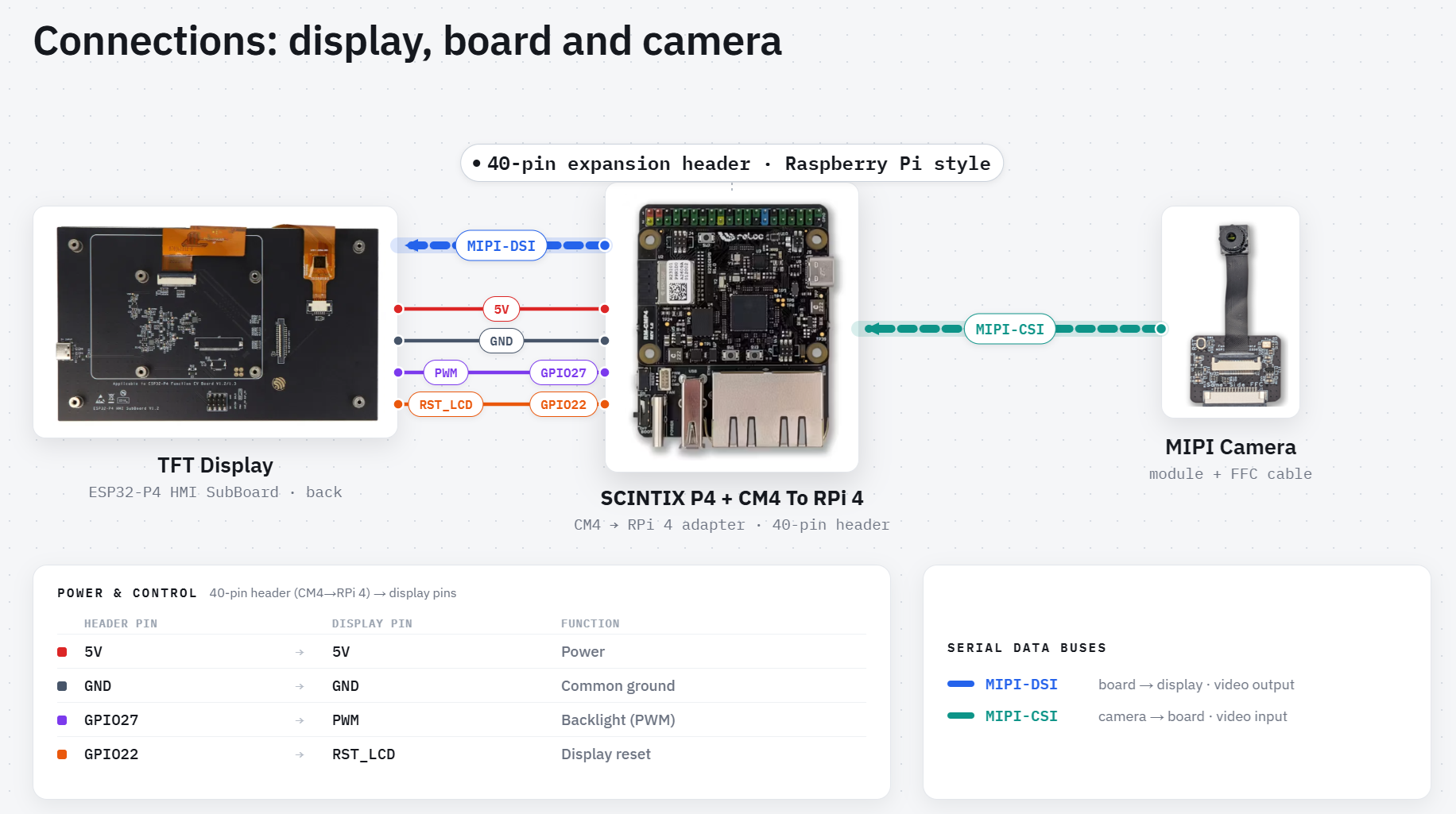
SCINTIX P4 gives you the ability to build multimedia applications powered by a real-time MCU.
It's a fast and versatile platform designed for display- and camera-based HMI applications over MIPI-DSI and MIPI-CSI. It's equally well suited to edge AI workloads, sensor-processing applications, and modular embedded systems that need the flexibility of a CM4/CM5 carrier while keeping the deterministic behavior of a microcontroller.
What you will learn in this tutorial- Project setup and build process
- Firmware flashing
- Camera integration
- Display integration
                        +-----------+
                        |  SCINTIX  |
                        +-----------+
                              |
                              v
                    +---------------------+
                    | CM4-to-Pi4-Adapter  | ─────────────────┐
                    +---------------------+                  |
                           |         |                       | SUPPLY/RST CABLE
              CAMERA CABLE |         | DISPLAY CABLE         |
                           v         v                       v
+-----------------------------+  +-----------------------------+
| ESP32-P4-Function-EV-Board  |  | ESP32-P4-Function-EV-Board  |
|           CAMERA            |  |           DISPLAY           |
+-----------------------------+ +-----------------------------+Connections
- Place the SCINTIX P4 board (already programmed — see the Firmware section below) onto the CM4-to-Pi4 adapter.
- Connect the camera and the display using the flat cables.
- Connect the supplementary cable from the CM4-to-Pi4 adapter to the display. This cable provides the display power supply and reset signal.
  | CM4-to-Pi4-Adapter Pin | Display Pin |
  |--------------------------------------|
  |           5V           |      5V     |
  |          GND           |     GND     |
  |         GPIO27         |     PWM     |
  |         GPIO22         |   RST_LCD   |
Project Structure
esp_brookesia_phone/
├── main/
│   ├── main.cpp               # entry point — BSP + framework init, app install
│   └── lvgl_adapter_init.c    # MIPI-DSI panel + GT911 touch → LVGL binding
├── components/
│   ├── apps/
│   │   ├── camera/            # MIPI-CSI streaming, AI detection, photo UI
│   │   ├── setting/           # WiFi, BLE toggle, brightness, SNTP
│   │   ├── game_2048/         # gesture input, NVS high-score
│   │   ├── music_player/      # SPIFFS file iterator, LVGL music demo
│   │   ├── calculator/        # LVGL keyboard, expression parser
│   │   └── video_player/      # SD card, MJPEG decoder
│   ├── human_face_detect/     # MSRMNP 2-stage face detection (esp-dl)
│   └── pedestrian_detect/     # Pico single-stage pedestrian detection (esp-dl)
├── spiffs/                    # MP3 assets (game sounds, music tracks)
├── partitions.csv             # nvs / phy_init / factory / storage
└── CMakeLists.txt
Software setup
Windows
- Install VS Code
- Install the ESP-IDF extension for VS Code (from Espressif). Once the correct extension is installed, you should see these icons and toolbar (1).
- Install ESP-IDF v5.5.4, as required by the example (steps 2.1 to 2.4).
- Clone the repository:
git clone https://github.com/relocsrl/scintix-p4.git- Open the `scintix-p4` folder.
- Launch VS Code from the `scintix-p4\examples\esp_brookesia_phone` folder.
Clink on explorer path, write `cmd` and press Enter
Type `code .` and press Enter
- Select the correct ESP-IDF v5.5.4 (3.1) and build (3.2).
- If everything is set up correctly, you should see the expected output in the terminal, with the target set to `esp32p4`.
- Connect the USB Type-C cable to the SCINTIX P4 board and press Flash (5.1). If needed, use the UART interface.
- Et voilà — the demo is up and running. The display now shows the Brookesia launcher with its smartphone-style interface, fully driven by the ESP32-P4 on the SCINTIX P4 module. From here, you can navigate the UI and explore the built-in apps.


Comments