

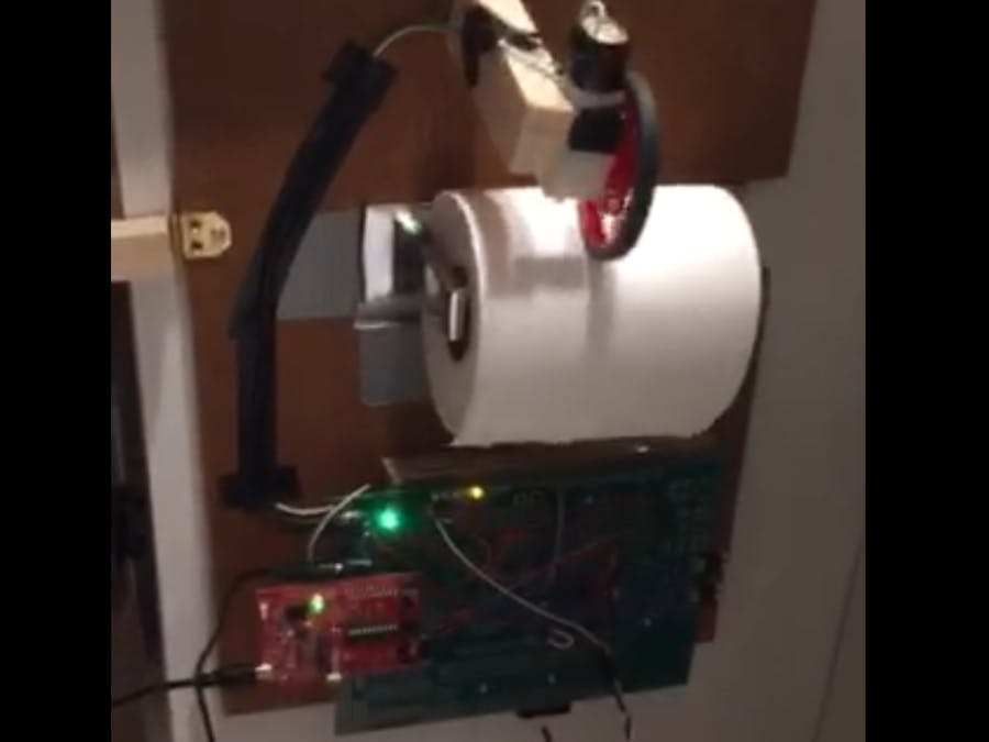

Using the Texas Instruments MSP430G2553 processor, a motor, and an IR sensor this toilet paper dispenser is designed to roll out 3 squares of toilet paper whenever there is anything less than 3 squares hanging free. An IR sensor below the roll of toilet paper senses the length of the toilet paper. If the amount of toilet paper is less than 3 squares then the sensor will send a command to run the motor and dispense more toilet paper. Once the toilet paper is long enough the sensor sends the command to stop running the motor and the user is left with 3 fresh and untouched squares of toilet paper.
This device makes you feel like true royalty when sitting on your porcelain throne!
/******************************************************************************
MSP430G2553 Project Creator

SE 423  - Dan Block
        Spring(2019)

        Written(by) : Steve(Keres)
College of Engineering Control Systems Lab
University of Illinois at Urbana-Champaign
*******************************************************************************/

#include "msp430g2553.h"
#include "UART.h"

void print_every(int rate);

char newprint = 0;
long NumOn = 0;
long NumOff = 0;
int statevar = 1;
int timecheck = 0;

//Reid's Variables
int ADC_ranged_value = 0; //This variable takes the range that the light sensor can sense and expands it to utilize the full 1023 range of values
int ADC_A0_A3_value = 0; //The variable used to store the ADC A0 or A3 value
int milivolts = 0; //The variable used to store the milivolt value of the ADC
int timecnt = 0; //Used to keep track of time passed

void main(void) {

    WDTCTL = WDTPW + WDTHOLD;                 // Stop WDT

    //if (CALBC1_16MHZ ==0xFF || CALDCO_16MHZ == 0xFF) while(1);
    if (CALBC1_1MHZ ==0xFF || CALDCO_1MHZ == 0xFF) while(1);

    //I slowed down the counter so that we could have the carrier frequency be 50Hz = 20ms
    //Even at 8MHz the carrier frequency would have been 160,000 which is still greater than the
    //65,535 max of a long int
    DCOCTL = CALDCO_16MHZ;//CALDCO_16MHZ;    // Set uC to run at approximately 1 Mhz
    BCSCTL1 = CALBC1_16MHZ;//CALBC1_16MHZ;

    // Initialize Port 1
    P1SEL |= 0x01;  //Initialized P1.0 to be TA0 (1)
    P1SEL2 = 0x0; //
    P1REN = 0x0;  //
    P1DIR |= 0x01; //Initialized P1.0 to be TA0 (1)
    P1OUT = 0x0;  //

    //Initializes P2.1 to be TA1 and P2.4 to be TA2
    P2SEL |= 0x04;   //For P2.2 to be TA1 and their SEL bits need to be set to 1
    P2SEL2 = 0x0; //
    P2REN = 0x0; //
    P2DIR |= 0x04; //For P2.1 to be TA1 and their DIR bits need to be set to 1
    P2OUT = 0x0; // Initially set all P2 pins to 0

    //Main initialization of the ADC10
    ADC10CTL0 = SREF_0 + ADC10SHT_1 + ADC10ON + ADC10IE;
    //Initialization of the ADC10 A3 channel
    ADC10CTL1 = INCH_0 + SHS_0 + ADC10DIV_0 + ADC10SSEL_0 + CONSEQ_0; //samples and sets up channel 0
    ADC10AE0 = 0x01;//allows channel A0 to be sampled

    // Timer A0 Config
    TA0CCTL0 = CCIE;            // Enable Periodic interrupt
    TA0CCR0 = 16000;                // period = 1ms/cycle @ 1MHz --> (1/1,000,000)s/cycle * x = 0.001s/cycle --> x = 1000
    TA0CTL = TASSEL_2 + MC_1; // source SMCLK, up mode

    //Timer A1 Config
    TA1CCR0 = 800;                             // period --> 1MHz(rate) = 1/1,000,000 s/cycle --> 50Hz = 50 cycle/s = 0.02 s --> 20 ms/cycle --> (1/1,000,000)x = 0.02 --> x = 20,000
    TA1CCTL1 = OUTMOD_7;                         // PWM output mode: 7 - PWM reset/set
    TA1CCR1 = 400;    // TA1CCR1 PWM duty cycle, initially set to 0 torque which is 400
    TA1CTL = TASSEL_2 + MC_1;                  // SMCLK, up mode

    Init_UART(115200,1);    // Initialize q  for 115200 baud serial communication

    _BIS_SR(GIE);       // Enable global interrupt
    //__bis_SR_register(GIE);       // Enable global interrupts

    while(1) {  // Low priority Slow computation items go inside this while loop.  Very few (if anyt) items in the HWs will go inside this while loop

// for use if you want to use a method of receiving a string of chars over the UART see USCI0RX_ISR below
//      if(newmsg) {
//          newmsg = 0;
//      }

        // The newprint variable is set to 1 inside the function "print_every(rate)" at the given rate
        if ( (newprint == 1) && (senddone == 1) )  { // senddone is set to 1 after UART transmission is complete

            // only one UART_printf can be called every 15ms
            //UART_printf("St%d On %ld Off %ld\n\r",statevar,NumOn,NumOff);

            newprint = 0;
        }

    }
}


// Timer A0 interrupt service routine
#pragma vector=TIMER0_A0_VECTOR
__interrupt void Timer_A (void)
{
    //ADC10 Enable Conversion & Starts Conversion
    ADC10CTL0 |= ENC + ADC10SC;
}


// ADC 10 ISR - Called when a sequence of conversions (A7-A0) have completed
#pragma vector=ADC10_VECTOR
__interrupt void ADC10_ISR(void)
{
    ADC_A0_A3_value = ADC10MEM;     //Takes the ADC10MEM value and puts it in the variable ADC_A0_A3_value
    milivolts = (ADC_A0_A3_value*3300L)/1023;       //converts the ADC10 value (0-1023) to milivolts

    //if the IR sensor reads greater than 100 then it stops the motor.The ADC values normally are around 70 or so.
    if(ADC_A0_A3_value > 400)
    {
        TA1CCR1 = 400;    // TA1CCR1 PWM duty cycle, %0 duty cycle. TA1CCR1 ranges from 0-800 with 400 being the middle which signifies neither forward nor backward movement
    }
    else
    {
        TA1CCR1 = 400 + (400 * 0.75);    // TA1CCR1 PWM duty cycle, %75 duty cycle. TA1CCR1 ranges from 0-800 with 400 being the middle which signifies neither forward nor backward movement
    }
}


// USCI Transmit ISR - Called when TXBUF is empty (ready to accept another character)
#pragma vector=USCIAB0TX_VECTOR
__interrupt void USCI0TX_ISR(void)
{

    if(IFG2&UCA0TXIFG) {        // USCI_A0 requested TX interrupt
        if(printf_flag) {
            if (currentindex == txcount) {
                senddone = 1;
                printf_flag = 0;
                IFG2 &= ~UCA0TXIFG;
            } else {
                UCA0TXBUF = printbuff[currentindex];
                currentindex++;
            }
        } else if(UART_flag) {
            if(!donesending) {
                UCA0TXBUF = txbuff[txindex];
                if(txbuff[txindex] == 255) {
                    donesending = 1;
                    txindex = 0;
                }
                else txindex++;
            }
        } else {  // interrupt after sendchar call so just set senddone flag since only one char is sent
            senddone = 1;
        }

        IFG2 &= ~UCA0TXIFG;
    }

    if(IFG2&UCB0TXIFG)
    {   // USCI_B0 requested TX interrupt (UCB0TXBUF is empty)

        IFG2 &= ~UCB0TXIFG;   // clear IFG
    }

}


// USCI Receive ISR - Called when shift register has been transferred to RXBUF
// Indicates completion of TX/RX operation
#pragma vector=USCIAB0RX_VECTOR
__interrupt void USCI0RX_ISR(void) {

    if(IFG2&UCB0RXIFG)
    {  // USCI_B0 requested RX interrupt (UCB0RXBUF is full)

        IFG2 &= ~UCB0RXIFG;   // clear IFG
    }

    if(IFG2&UCA0RXIFG)
    {  // USCI_A0 requested RX interrupt (UCA0RXBUF is full)

//    Uncomment this block of code if you would like to use this COM protocol that uses 253 as STARTCHAR and 255 as STOPCHAR
/*
        if(!started)
        {   // Haven't started a message yet
            if(UCA0RXBUF == 253)
            {
                started = 1;
                newmsg = 0;
            }
        }
        else
        {       // In process of receiving a message
            if((UCA0RXBUF != 255) && (msgindex < (MAX_NUM_FLOATS*5)))
            {
                rxbuff[msgindex] = UCA0RXBUF;

                msgindex++;
            }
            else
            {   // Stop char received or too much data received
                if(UCA0RXBUF == 255)
                {   // Message completed
                    newmsg = 1;
                    rxbuff[msgindex] = 255; // "Null"-terminate the array
                }
                started = 0;
                msgindex = 0;
            }
        }
*/

        IFG2 &= ~UCA0RXIFG;
    }

}

// This function takes care of all the timing for printing to UART
// Rate determined by how often the function is called in Timer ISR
int print_timecheck = 0;
void print_every(int rate) {
    if (rate < 15) {
        rate = 15;
    }
    if (rate > 10000) {
        rate = 10000;
    }
    print_timecheck++;
    if (print_timecheck == rate) {
        print_timecheck = 0;
        newprint = 1;
    }

}


Comments