

In this laboratory activity, I learned how to use timers, interrupts, and task scheduling on the STM32F407ZGT6 microcontroller. The main goal was to understand how interrupts work, how multiple tasks can run in a system, and how different scheduling methods affect task performance.
First, I configured a timer interrupt to automatically toggle an LED. Next, I added another timer and created multiple tasks that run at different time intervals. I then measured timing parameters such as TRelease, TLatency, TISR, and TResponse to see how the system performs. Lastly, I implemented an event-triggered system using a push button and compared its behavior with the timer-based system.
Part1: Configure Hardware Timer with Interrupts
A new STM32 project was created using STM32CubeMX. The software was opened, and a new project was created for the STM32F407ZGT6 microcontroller.
The STM32F407ZGT6 microcontroller, which is used on the RT-Spark development board, was searched for and selected in STM32CubeMX. This allowed the project to be configured for the correct microcontroller and hardware platform. After that, click "Start Project".
The STM32CubeIDE toolchain was also selected so that the generated code could be opened, edited, compiled, and uploaded to the STM32F407ZGT6 microcontroller.
The onboard LEDs were configured as GPIO outputs so they could be controlled by the program. Pin PF11 was assigned as LED_RED, while pin PF12 was assigned as LED_BLUE. These pins were set as output pins in STM32CubeMX, allowing the microcontroller to turn the LEDs on and off during execution.
The TIM2 timer was set up to generate an interrupt every 1 second. The timer settings were adjusted to produce a 1 Hz signal, and the TIM2 interrupt was enabled with the highest priority. After the configuration was completed, the project code was generated.
ImplementationPart 2: Implement Timer ISR for Periodic LED Toggle
The generated project was opened in STM32CubeIDE. The main.c file was then accessed by navigating to Core to Src to main.c, where the main() function was located for adding the required code.
The code HAL_TIM_Base_Start_IT(&htim2) was added before the infinite loop to start TIM2 with interrupts enabled. This allows the timer to begin counting and automatically generate an interrupt whenever the set timer period is reached.
A timer callback function was implemented to handle the TIM2 interrupt. Whenever the timer reaches its set period, the callback function is automatically executed and toggles the red LED (PF11). This causes the LED to blink once every second.
The activity was built and uploaded to the RT-Spark development board. After running the program, the red LED was observed blinking every 1 second, confirming that the timer interrupt was working correctly.
Part 3: Create Multi-Task Cyclic Executive System
A second timer, TIM3, was configured to create another periodic interrupt with a different rate. The timer was set to generate an interrupt every 0.5 seconds and was assigned a lower priority than TIM2. After the configuration was completed, the project code was regenerated to apply the changes.
Global variables were added to help the interrupts and main loop share information. The variables task_adc_ready and task_display_ready were used to indicate when a task is ready to run, while tick_count was used to count timer events.
The callback function was updated so that TIM2 toggles the red LED and signals Task A, while TIM3 toggles the blue LED and signals Task B. This lets the main loop know when each task is ready to run.
The main loop was updated to run tasks when their flags were set. Task A simulates ADC processing, while Task B simulates a display update.
Part 4: Measure and Analyze Response Times
A debug pin (PE0) was configured as a GPIO output and labeled DEBUG_PIN.
Timing markers were added using the DEBUG_PIN. The pin was set HIGH when the interrupt or task started and set LOW when it finished.
Part 5: Implement Event-Triggered SchedulingThe PA0 button was set up as an interrupt input. This allows the microcontroller to react whenever the button is pressed. After the setup was finished, the project code was regenerated.
An external interrupt callback function was added to detect button presses. When the PA0 button is pressed, the function immediately toggles both the red LED and blue LED.
Testing the button interrupt operation.The project was tested by uploading it to the board. The LEDs continued blinking based on the timer interrupts. When the button was pressed, both LEDs changed state immediately, showing that the button interrupt was working.
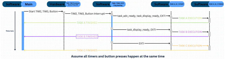
AnalysisIn this activity, timer-based and event-triggered scheduling were used. In the timer-based approach, tasks run when the main loop checks their flags, so there can be some waiting time. In the event-triggered approach, tasks run right away when an event happens, such as a button press.
The event-triggered approach responds faster, while the timer-based approach is useful for tasks that need to run regularly.


Comments