


Hardware components | ||||||
| × | 1 | ||||
 |
| × | 1 | |||
 |
| × | 1 | |||
 |
| × | 1 | |||
 |
| × | 4 | |||
 |
| × | 4 | |||
 |
| × | 4 | |||
 |
| × | 1 | |||
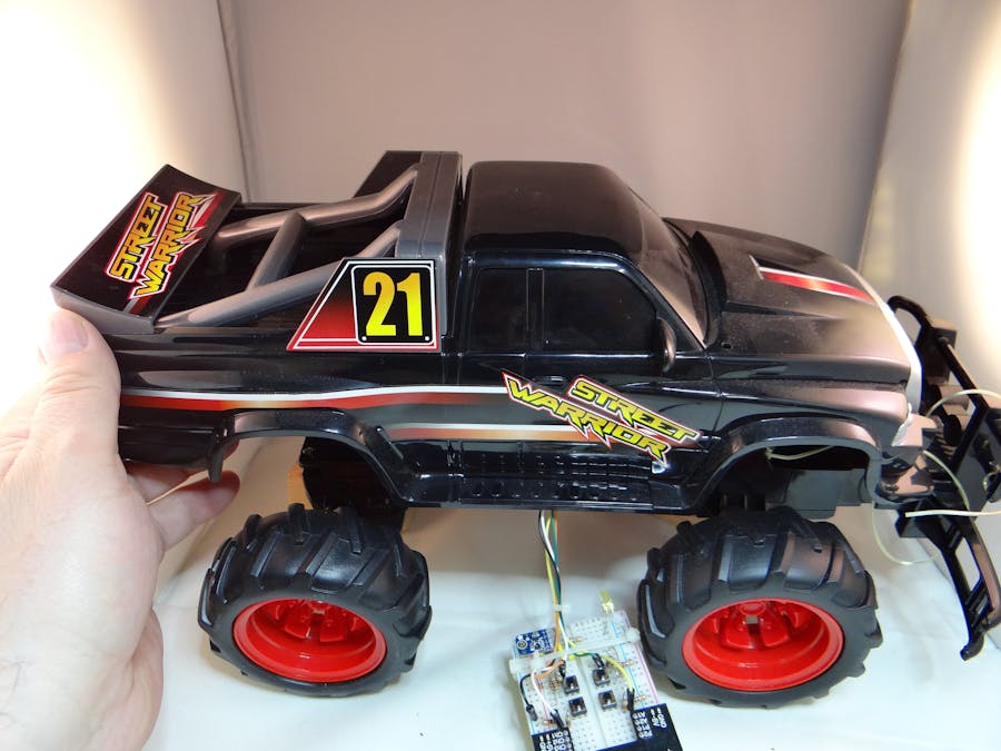
Troy first came up with the idea of hacking the hardware on an RC car to get control of the motor controller circuits as a way to get an inexpensive and fun car chassis, motors, and controller to build a smart car robot. One can buy the kits with motors, chassis, and wheels, however, they are challenging to assemble and slow compared to these cheap RC cars.
With an off-the-shelf RC car you get:
- Awesome chassis, choice of colors, choice of model and make
- Motors, tires, chassis, battery compartment, and/or rechargable batteries
- Fast and powerful motors
- A durable framework that can be operated outside
This is not the first time it's been done, but, this time we will take it further and use a Cypress PSoC controller to make the brains of the robot. Fortunately for us, most of these RC cars use a common H-bridge motor controller.
The first installation of this project shows how to hack the hardware motor controller to get control of the signals that control motor direction and steering. Speed will be controlled using the PWM on the PSoC.
See the power point attachment for the challenge to make the car go.
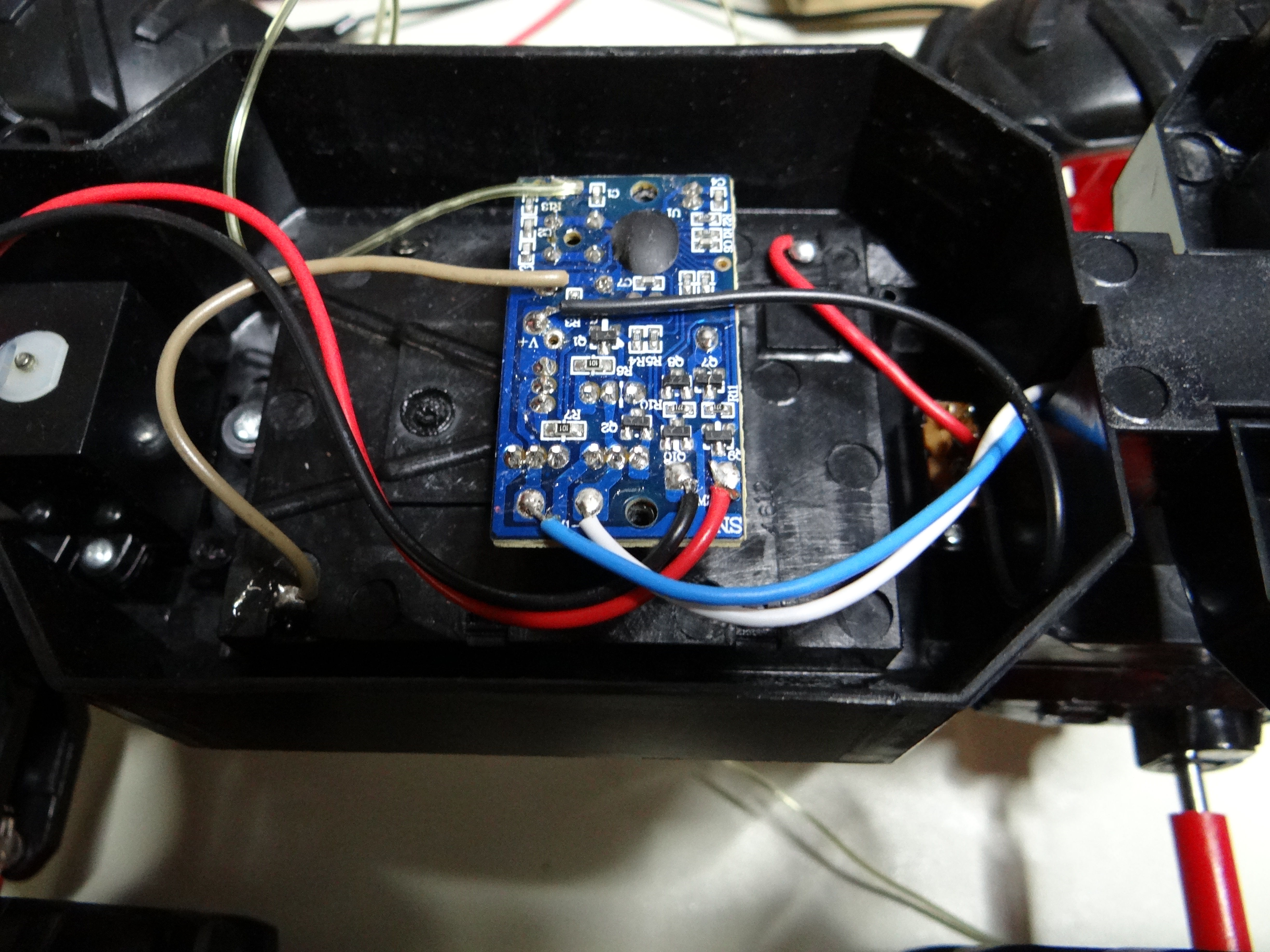
Typical RC car motor controller
I drew circles around the electrical nets from the integrated circuits where we will hack into the motor controller and disconnect it from the remote control decoder integrated circuit.
I removed "R13, R14, R15, and R16" from the motor controller board to disconnect the on-board remote controller integrated circuit. In the next schematic I will show how I took control of the motor controller using switches.

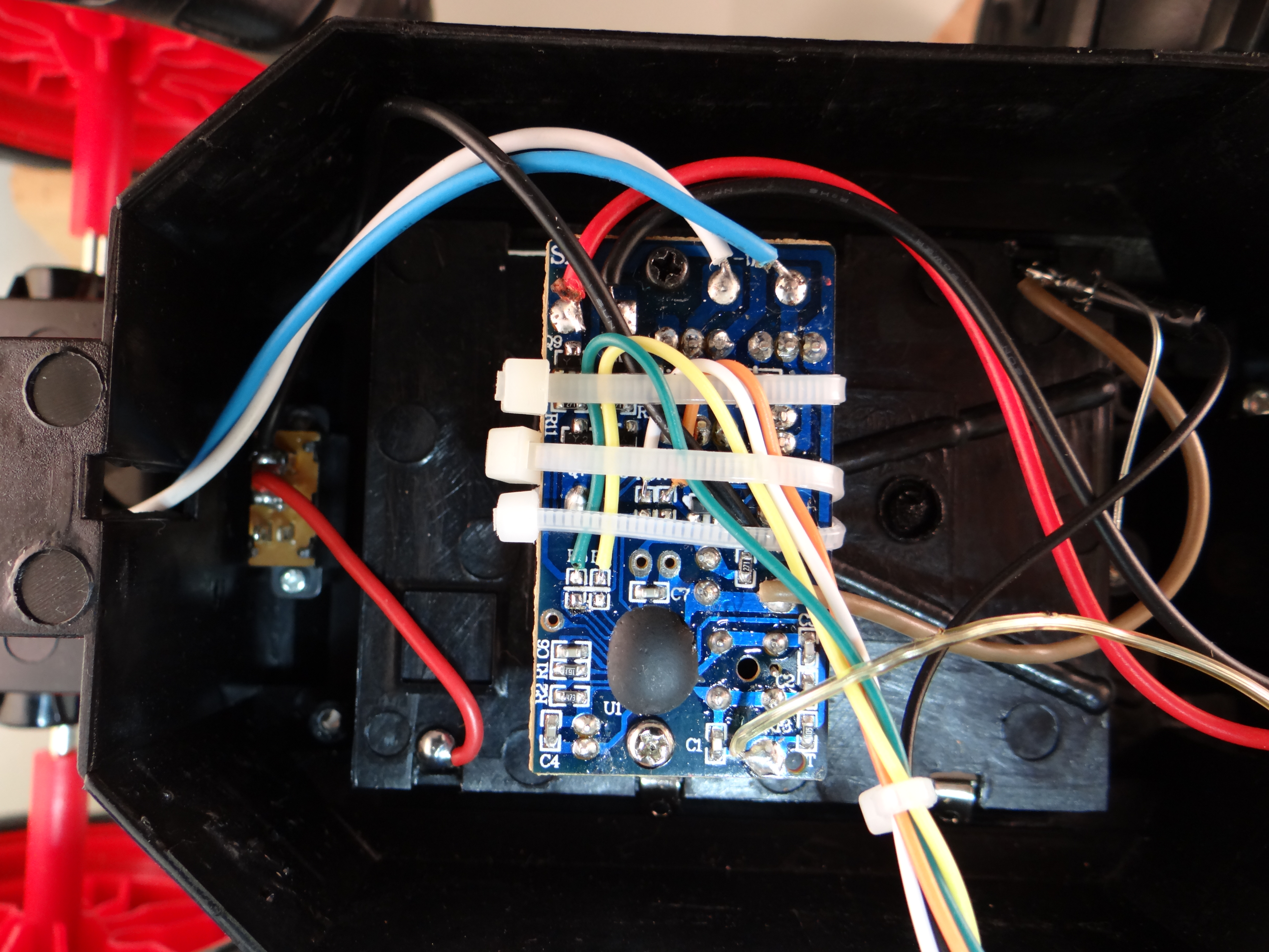
Remove resistors from RC car motor controller board
I was able to determine that those four resistors are the equivalent to R13, R14, R15, and R16 on the schematic. I used a volt meter to look at the voltage output from the remote controller integrated circuit to the resistors and then by flipping the controls on the remote controller determine which resistor performed which function. Then, I removed the tiny resistors with a soldering iron tip being careful not to damage the pads on the circuit board.
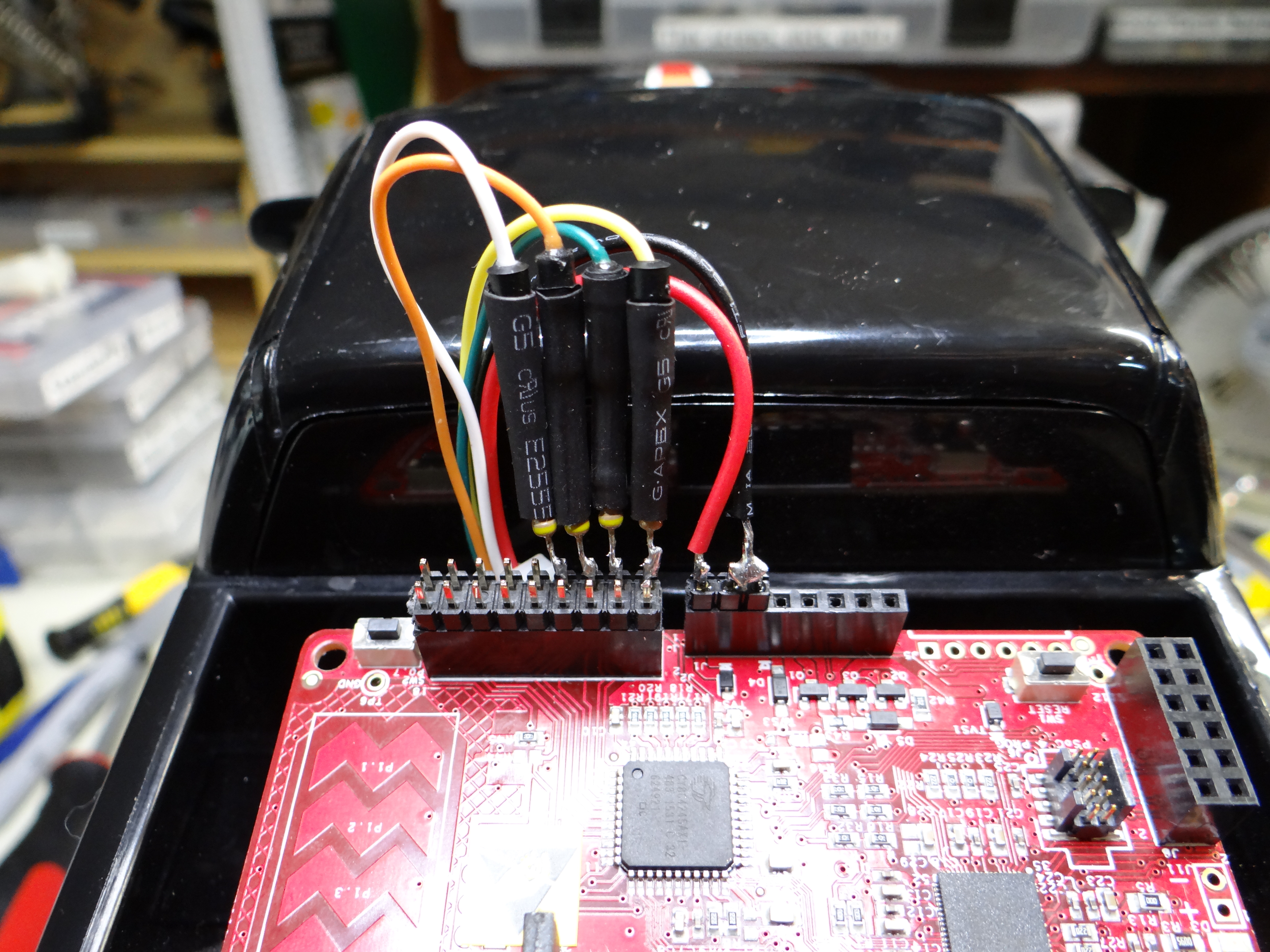
Wiring to the motor controller board
The new wires represent control as such:
Yellow = steer right
Green = steer left
Orange = rear wheels forward
White = rear wheels reverse
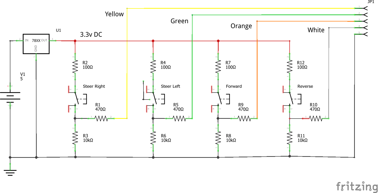
Breadboard schematic
WARNING: H bridges are highly susceptible to being toasted (i.e. burned out, flame out, smoke released, etc.) If you turn on two switches at the same time, such as forward and reverse, you will short power to ground through the H-bridge transistors, thus exceeding the collector current rating for both transistors. The tiny little silicon traces inside the transistors don't like that and will POP! The same thing can happen if you miss wire the breadboard, so, be careful and test it with a volt meter before you hook it up to the RC car motor controller.
WARNING 2:
The 470 ohm current limiting transistor has a very important purpose of limiting the base current to the transistors in the H-bridge. The 100 ohm resistor will probably protect them for a while, but you don't want to exceed the base current on the transistors for long; they will POP too.
PSoC wired to motor controller
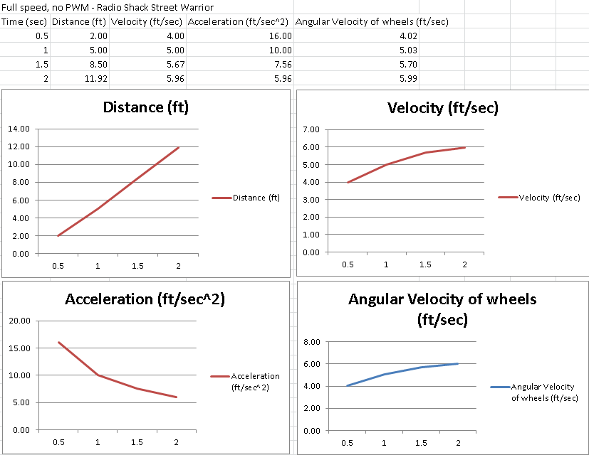
Empirical velocity and acceleration measurements


_3u05Tpwasz.png?auto=compress%2Cformat&w=40&h=40&fit=fillmax&bg=fff&dpr=2)


Comments