


Hardware components | ||||||
| × | 1 | ||||
| × | 1 | ||||
| × | 1 | ||||
 |
| × | 1 | |||
 |
| × | 1 | |||
Software apps and online services | ||||||
 |
| |||||
| ||||||
| ||||||
Hand tools and fabrication machines | ||||||
 |
| |||||
I’ve always been interested in voice assistants, but most of the time they are stuck inside phones or big smart speakers. I wanted something smaller… something I could actually keep on my desk or carry around with me.
So I decided to build my own using an ESP32. At first it felt a bit complicated, but after discovering Xiaozhi firmware, things became much easier. I didn’t have to deal with heavy coding — just flash the firmware and set it up.
The result is a pocket-size AI voice assistant that can listen, respond, and even display information on a small screen. It feels more like a real device than just a project.
What You Can Do With ItThis little device can actually be used in many ways:
- You can use it as a simple smart home assistant to check weather or control devices
- It works as a learning companion for asking questions or quick explanations
- You can use it for fun interactions like chatting, stories, or basic entertainment
- It’s also great as a developmnt platform if you want to experiment with AI and voice projects
- And it can act as an IoT interface inside bigger smart systems
I didn’t build this in one go.
- First I tested everything on a breadboard, then I made a compact PCB version.
For testing, I used only basic parts:
- ESP32-S3 development board (Amazon.com / Aliexpress.com)
- INMP441 microphone (Amazon.com/ Aliexpress.com)
- MAX98357A amplifier (Amazon.com/ Aliexpress.com)
- Small speaker (4Ω–8Ω, 2–3W) (Amazon.com)
- OLED display (SSD1306, 0.91” / 0.96”) (Amazon.com)
- Push button
- Breadboard + jumper wires
This was enough to test voice input, AI response, and audio output.
PCB VersionAfter it worked, I moved to a PCB to make it small and clean.
Components I used on PCB:
- ESP32-S3 (main controller)
- INMP441 digital microphone
- MAX98357A I2S amplifier
- OLED 0.96” (SSD1306 – HS96L03W2C03)
Buttons & Switch:
- Reset button (K2-1109DE)
- 3 tactile buttons (Boot, Vol+, Vol− – KH-4.5X4.5X6H)
- Power switch (SK12D07L3B)
Connectors:
- 2.54mm female headers (I2C / OLED / ESP32)
- 2x22 pin headers for ESP32 mounting
- Speaker connector (1.25mm 2-pin – ZX-MX1.25)
This made the whole project much more compact and practical. Now it actually feels like a proper pocket device instead of a prototype.
How It WorksBefore building, it helps to understand what’s actually going on behind the scenes.
This project doesn’t run AI directly on the ESP32. Instead, it uses cloud-based processing, which is why even a small board can act like a smart assistant.
The working flow is like this:
First, you speak into the microphone.
The ESP32 records your voice using I2S audio input.
Then it sends that audio over WiFi to the Xiaozhi cloud.
On the cloud side, all the heavy work happens:
- Your voice is converted into text (Speech-to-Text)
- The AI model understands it and generates a reply
- That reply is converted back into voice (Text-to-Speech)
After that, the audio response is sent back to the ESP32.
Finally, the ESP32 plays it through the speaker.
So in simple terms, the ESP32 is handling:
- Recording and playing audio
- Connecting to WiFi
- Managing the device
And the actual AI thinking happens in the cloud.
That’s why even a small microcontroller like ESP32 can run a powerful voice assistant without needing heavy processing on the device itself.
Step 2: Understanding the HardwareBefore starting the wiring, I spent some time understanding what each part actually does. It makes things much easier later.
The INMP441 microphone is a digital mic that uses I2S. Instead of giving analog signals, it sends digital audio directly to the ESP32. Because of that, it has less noise and gives better audio quality.
The MAX98357A amplifier also works on I2S. It takes digital audio from the ESP32 and directly drives the speaker. The good part is that it doesn’t need any extra DAC, so the circuit stays simple.
The ESP32-S3 is the main controller of the whole project. It handles WiFi, records audio from the mic, sends it to the cloud, and plays back the response.
The OLED display is just for feedback. It shows things like status, messages, or connection info. Not required, but it makes the project feel more complete.
One interesting thing here is that both input and output use I2S.
So the same type of audio interface is used for the microphone and the speaker, which makes it perfect for this kind of voice project.
Step 3: ESP32-S3 Development BoardThe ESP32-S3-DevKitC-1 is the main controller used in this project. It’s a powerful and flexible development board based on Espressif’s ESP32-S3 chip.
It comes with built-in WiFi and Bluetooth, which makes it perfect for IoT and AI-based projects. It has enough performance to handle things like audio processing and communication with cloud services.
At its core, it uses a dual-core Xtensa LX7 processor running up to 240 MHz. It also supports basic hardware acceleration for AI tasks, which helps in applications like voice interaction.
Specification:-- Microcontroller: ESP32-S3
- CPU: Dual-core Xtensa LX7 Running at up to 240 MHz
- USB Ports: Dual Type-C For Data and Power
- Wireless Connectivity: Wi-Fi (802.11b/g/n), Bluetooth (BLE)
- Flash : 8 MB QD
- SPI Voltage : 3.3 V
- Module Integrated : ESP32-S3-WROOM-1-N16
- Frequency: 2.4 GHz
- Interface Type: GPIO, UART, USB
- Protocol Supported: 802.11 b/g/n
- Connectivity Technology: Bluetooth, Wi-Fi, USB
- GPIO Pins: 34
The MAX98357A is a small but powerful digital audio amplifier used to drive the speaker in this project.
Instead of using analog audio, it works directly with I2S digital audio, which makes the circuit much simpler and cleaner. You don’t need a separate DAC because this module already converts digital audio into sound and amplifies it at the same time.
That’s why it’s commonly used in smart speakers, portable audio devices, and voice projects like this.
How It Works (Simple Idea)The ESP32 sends digital audio data through I2S.
The MAX98357A:
- Converts that digital signal into analog audio
- Amplifies it
- Sends it directly to the speaker
So basically, it combines DAC + Amplifier in one module.
Key Technical Details- Supply Voltage (V_DD): 2.5V to 5.5V
- Output Power: 3.2W into 4Ω at 5V
- Digital Audio Interface: I²S
- THD+N: 0.1% (Typical at 1kHz)
- SNR: 90dB (Typical)
- Efficiency: Up to 92%
NMP441 - ->ESP32
- VIN → 3.3V
- GND → GND
- DIN → GPIO7 (audio data)
- BCLK → GPI015
- LRC → GPI016
- GAIN→ GND
- SD → 3.3V
Speaker connects directly to:
- SPK+
- SPK−
The INMP441 is the microphone used in this project to capture your voice.
It’s a digital MEMS microphone, which means it already has built-in amplification and analog-to-digital conversion. So instead of sending noisy analog signals, it directly sends clean digital audio to the ESP32 using I2S.
That’s why it works really well for voice projects like this.
How It WorksWhen you speak, the microphone captures the sound and converts it into digital data.
This data is sent to the ESP32 through the I2S interface using three main signals:
- SCK → clock
- WS → left/right sync
- SD → audio data
So no extra ADC or complex circuit is needed.
Why I Used This Mic- Digital output → less noise compared to analog mics
- Works directly with ESP32 (I2S)
- Small and easy to use
- Good sensitivity for voice input
- Low power consumption
Here’s how I connected it With esp32
NMP441 - ->ESP32
- VDD → 3.3V
- GND → GND
- WS → GPIO4 (word select)
- SCK → GPIO5 (clock)
- SD → GPIO6 (data out)
- L/R → GND (for mono / left channel)
- Works on 3.3V only
- L/R pin decides left or right channel (I used GND for simple setup)
- It’s a mono microphone
- Try to keep wiring short for better audio quality
For displaying information, I used a small OLED screen based on the SSD1306 driver.
These displays are very common in DIY projects because they are small, clear, and easy to use. Even though the size is tiny, the text looks sharp and easy to read.
It connects using the I2C interface, so only two data lines are needed, which makes wiring simple.
- High contrast → text is very clear
- Low power → good for portable projects
- Small size → perfect for compact builds
- Easy to use → lots of libraries available
The connections should be as follows:
ESP32 - ->OLED
3.3V --->VCC
GND -->GND
GPIO41----> SDA
GPIO42----> SCL
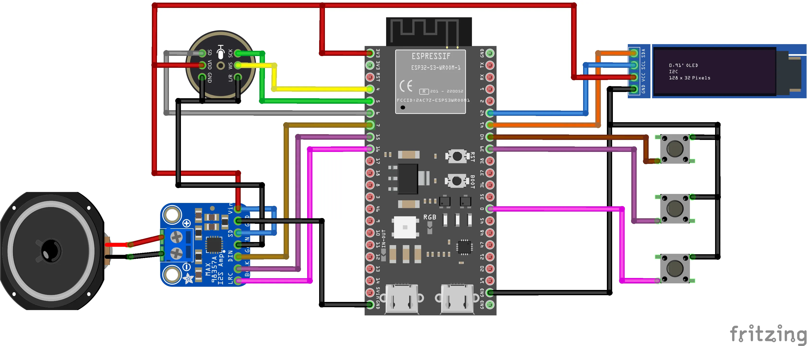
Step 7: Make the CircuitNow just follow the circuit diagram shown in the image above.
I’ve already explained all the connections for each component, so you can wire them step by step. To make things easier, I also built it on a breadboard.
Here you can see the full setup in the photo. Just connect everything carefully and double-check the pins before powering it on.
Flashing the Xiaozhi FirmwareNow let’s upload the Xiaozhi firmware to the ESP32.
1. Download Files
First, download these:
- ESP Flash Download Tool
- https://docs.espressif.com/projects/esp-test-tools/en/latest/esp32/production_stage/tools/flash_download_tool.html
- My Project Repository (Firmware + Files)
- https://github.com/Rau7han/esp32-ai-pocket-assistant
This repo has everything you need, including the firmware file.
2. Setup Flash Tool- Extract all the downloaded files
- Open the ESP Flash Download Tool
- Select chip type → ESP32-S3
Now comes the main part.
- Click on the “…” button and select the firmware file
- (merged-binary.bin) from the project folder
- Set address to: 0x0
- Tick the checkbox next to the file
- Select the correct COM port
Then:
- Click Erase and wait until it finishes
- Click Start
Wait a few minutes until it shows FINISH.
WiFi Setup and Device ActivationAfter flashing the firmware, now it’s time to connect the device and make it ready.
Power On and Connect
Turn on your device.
After booting, it will create its own WiFi hotspot like:
Xiaozhi-XXXX
Open WiFi settings on your phone or laptop and connect to it.
Open Setup PageOnce connected, open your browser and go to:
192.168.4.1
This will open the configuration page.
Connect to Your WiFi- Select your WiFi network (2.4GHz only)
- Enter password
- Click Connect
If everything is correct, the device will connect and restart automatically.
Get Device CodeAfter restarting, the device will speak (or show) a 6-digit code.
This code is needed to link your device.
Add Device to XiaozhiNow go to:
- Create an account or log in
- Open Console
- Click Add Device
- Enter the 6-digit code
Now your device will appear in your dashboard.
Customize Your AssistantYou can now customize your AI:
- Change name
- Select language
- Choose voice
- Set personality (fun, professional, etc.)
- Select AI model
Save the settings.
Testing on BreadboardNow that everything is set up, it’s time to test it on the breadboard.
Restart the device once, and wait for it to connect to WiFi.
After that, try pressing the button (or use wake word if enabled) and speak something simple like:
“Hello” or “What can you do?”
If everything is connected properly:
- The microphone will capture your voice
- After a second, you should hear a reply from the speaker
- The OLED may show status or messages
The first time I tested it, I was honestly not sure if it would work 😅
But when it replied back, that felt really satisfying.
If It Doesn’t WorkDon’t worry, just check a few things:
- WiFi is connected properly
- Wiring is correct (especially I2S pins)
- Speaker and amplifier connections
- Power supply is stable
Most issues usually come from wiring mistakes.
PCB VersionAfter testing everything on the breadboard, I realized the wiring was getting really messy and not practical for daily use.
So I decided to move to a PCB to make it cleaner, more stable, and compact.
I didn’t design this PCB myself. I found a really nice open-source design online, so full credit goes to the original creator. surferlong
I liked this design because it already had everything well organized — proper placement for the ESP32, microphone, amplifier, buttons, and display. It also made the whole setup small enough to actually carry around.
Instead of redesigning everything, I directly used this PCB and ordered it. It saved a lot of time and effort.
Once I got the board, I just assembled all the components on it, and the difference was huge compared to the breadboard version.
Everything became:
- much cleaner
- more reliable
- and way more compact
Now it actually feels like a proper pocket device instead of a prototype.
PCB Fabrication – NextPCBFor this project, I ordered my PCB from NextPCB using the open-source Gerber files.
I went with the standard blue solder mask with white silkscreen. The boards arrived within about a week, and the quality was really good. The finish was clean, holes were accurate, and everything aligned perfectly, making the final build look much more professional compared to the breadboard setup.
NextPCB also provides a tool called HQDFM, which I found quite useful. It’s a free online Gerber viewer and DFM (Design for Manufacturing) analysis tool. You can upload your design and quickly check for possible issues before ordering.
I personally like using it because it avoids waiting for manufacturer feedback. You can do a quick self-check and fix mistakes early. The online viewer is fine for a basic preview, and for more detailed analysis (especially PCBA), there’s also a desktop version available.
They also have an accelerator program where you can get free assembled PCBs for selected projects:
https://www.nextpcb.com/blog/rp2040-free-pcba-prototypes-nextpcb-accelerator
Overall, my experience was smooth. Good PCB quality, fast delivery, and helpful tools like HQDFM made the whole process easier. If you’re building PCB-based projects, it’s worth checking them out.
PCB AssemblyFor this step, you’ll need a basic soldering setup: a soldering iron, solder wire, a nipper, and optionally a multimeter for checking connections.
Start by soldering components in order of their height. This makes assembly easier and keeps everything aligned properly.
Step-by-Step Assembly- Solder the pin headers first
- Insert the female headers into the PCB (as shown in the images) and solder them from the backside. These will hold the ESP32-S3 board in place.
- Mount and solder the push buttons
- Place the buttons in their respective positions on the PCB and solder all pins properly.
- Add smaller components (like modules)
- Solder modules like the microphone board carefully, making sure all pins are properly connected.
- Attach the ESP32-S3 board
- Once headers are in place, mount the ESP32-S3 board on top. Make sure alignment is correct before soldering (if required).
- Solder the TP4056 charging module (Back Side)
- Flip the PCB and solder the TP4056 module on the backside as shown in the images.
- This handles battery charging, so ensure:
- Correct polarity (+ / -)
- Strong solder joints
- Speaker and other connections
- Connect the speaker wires to the PCB pads or connector provided.
After assembling everything, the device powered up without any issues.
Since I had already flashed the firmware earlier, it started working immediately after turning it on. The ESP32-S3 boots up, initializes all modules, and the AI assistant becomes ready to use.
The microphone captures voice input, processes it, and the device responds through the speaker. The buttons also work for control, and overall the system feels smooth and responsive.
Everything came together nicely once moved from breadboard to PCB — much cleaner, compact, and reliable.
ConclusionThis project is a simple but powerful example of combining AI with embedded hardware.
It’s not just a circuit — it’s a small standalone AI device that can listen, respond, and interact in real time. And the best part is, it runs completely on an ESP32-S3 without needing any complex setup.
I didn’t design the PCB myself, but using an open-source design and building on top of it made the whole process much faster and easier.
For me, this project was more about learning and experimenting — understanding how voice, AI, and hardware can work together in a compact form.
It also shows that you don’t need expensive hardware to build something interesting. With the right components and open-source resources, you can create your own smart devices.
Overall, it turned out to be a clean, portable, and practical build.


Comments