


Hardware components | ||||||
 |
| × | 1 | |||
 |
| × | 1 | |||
 |
| × | 1 | |||
Software apps and online services | ||||||
 |
| |||||
| ||||||
Hand tools and fabrication machines | ||||||
 |
| |||||
 |
| |||||
I realized both plants and reptiles need proper environment control. At first I thought it’s simple — just give water, light, and that’s it. But after some time I realized they actually need proper temperature, humidity, day/night cycle, and even moisture control.
So instead of checking everything again and again manually, I decided to build a smart terrarium system that can handle most of it automatically.
This project is a fully automated smart terrarium system built using an ESP32. It monitors environmental conditions and automatically controls watering, humidity, and airflow while providing a modern web dashboard for remote control.
This project controls:
- Day/Night lighting
- Humidity using mist
- Temperature using a fan
- Moisture level (to avoid mold)
Sponsored by NextPCB
This project was successfully completed with the support of NextPCB, a reliable multilayer PCB manufacturer. With over 15 years of experience in PCB fabrication and assembly, NextPCB offers high-quality and dependable PCB solutions for makers and professionals worldwide.
You can order high-quality PCBs starting at $1.9, and multilayer PCBs starting at $6.9:
https://www.nextpcb.com/pcb-quote
Get free PCB assembly for up to 5 boards:
https://www.nextpcb.com/pcb-assembly-quote
With comprehensive Design for Manufacture (DFM) analysis features, HQDFM is a free, sophisticated online PCB Gerber file viewer.
SuppliesI tried to keep it simple and mostly used common components:
- ESP32 (with OLED display)
- Hi-Link AC to DC module
- DHT11 sensor
- Soil Moisture Sensor
- Mist maker module
- 5V fan
- Water Pump
- WS2812B LED ring
- 3-Channel Relay module
- Breadboard or PCB
- Push Button
- Jumper wires
- 3D printed mist holder
- Old aquarium
- Power Supply (5V Hi-Link or USB)
Tools Used:
1. Soldering Iron
2. Nipper
3. Wire Stripper
4. 3D Printer
That’s pretty much it. You can upgrade parts later if you want.
Enclosure:
- Old aquarium (any size — I used a standard small one)
- 3D printed mist holder (STL and print settings in Step 4)
Before starting the build, I first tried to understand what I actually needed in a terrarium.
At the beginning, I thought it’s just about watering plants or adding light, but it’s not that simple. Plants (and even reptiles) need a proper environment — temperature, humidity, light cycle, and moisture all need to stay in a good range.
The control logic works like this:
- Soil moisture below 30% → water pump turns ON
- Soil moisture above 50% → pump turns OFF
- Humidity below threshold → mist maker turns ON
- Temperature above threshold → fan turns ON
- Sensor failure or invalid reading → everything turns OFF (fail-safe)
To avoid rapid ON/OFF switching the system uses hysteresis — meaning it waits until a value clearly crosses the threshold before switching, rather than reacting to every small fluctuation. This protects your relay module and makes the system more stable.
The OLED display shows current readings and system status. The LED ring also gives a quick visual status:
🟢 Green → All normal
🔵 Blue → Pump is ON (watering)
🟣 Purple → Mist is ON
🔴 Red → Sensor error
The web dashboard runs directly from the ESP32 — no cloud, no external server needed. Open the IP address shown on the OLED in any browser on the same WiFi and you get full control.
There are two operating modes:
- AUTO mode — system runs itself based on sensor values and your set thresholds
- MANUAL mode — you control the fan, mist, and pump directly from the dashboard
A push button on the board also lets you switch modes with a short press, or trigger an emergency stop with a long press.
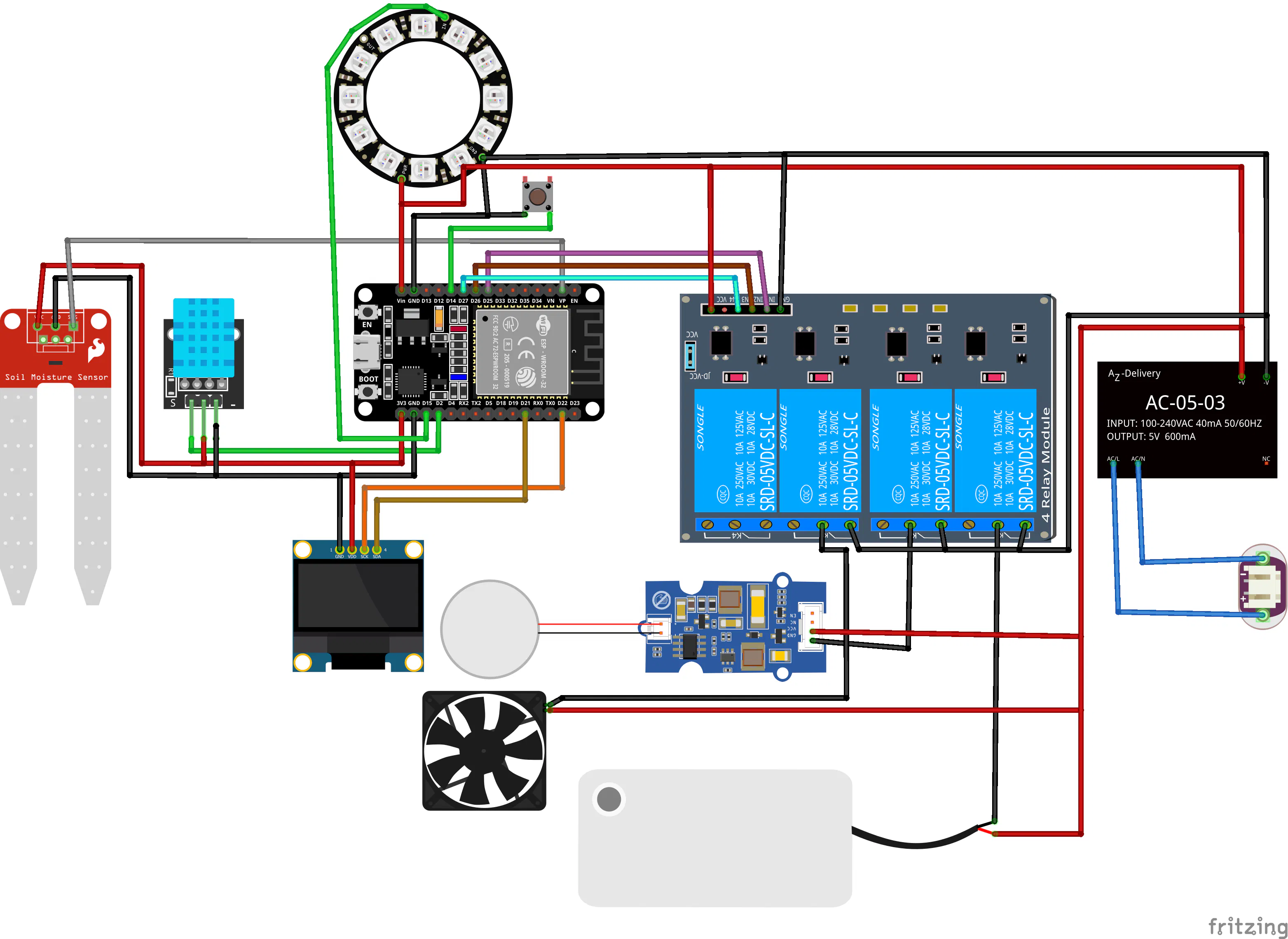
Step 2: Wiring DiagramFollow the schematic diagram provided above, or use the pin mapping listed below for reference.
OLED Display->ESP32
- SDA → GPIO 5
- SCL → GPIO 4 (If using an external OLED, use GPIO 21 for SDA and GPIO 22 for SCL instead)
DHT11 Sensor
- GPIO12 → DATA
- 3.3V → VCC
- GND → GND
Soil Moisture Sensor
- GPIO13 → Analog Output (AO)
- 3.3V → VCC
- GND → GND
Push Button
- GPIO14 → Button
- Other side → GND
- (uses INPUT_PULLUP)
WS2812 LED
- GPIO15 → DIN
- 5V → VCC
- GND → GND
Relay Module (3-Channel)
- GPIO25 → Relay 1 → Fan
- GPIO26 → Relay 2 → Water Pump
- GPIO16 → Relay 3 → Mist Maker
Relay VCC → 5V
Relay GND → GND
Power
- 5V from Hi-Link module → ESP32 VIN, Relay VCC, WS2812B VCC
- All GND lines → common ground📷
The wiring for this project is simple and direct. You need to connect all components (OLED display, DHT11 sensor, soil moisture sensor, WS2812 LED ring, button, and relay modules) to the ESP32 (Wemos Lolin32) according to the pin configuration.
Make sure all GND connections are common, otherwise the system may not work properly.Step 3: Preparing the Main Board
Start by laying out your perfboard and planning component placement before soldering anything.
Place the Hi-Link module first since it's the largest and defines your power distribution. Leave enough space around it — you don't want other components too close to the AC input side.
Next, place pin headers for the ESP32 so it can be removed if needed. Place screw terminals or pin headers for the relay module connections and the outgoing wires to the fan, pump, and mist maker.
Once you're happy with the layout, solder the power rails first — 5V and GND tracks along the edges of the board. Then solder in the headers and connectors.
After soldering, check the back of the board for any solder bridges between pads. Use a multimeter in continuity mode to confirm 5V and GND are not shorted before powering on.
Plug in the ESP32 board and power it up through USB first (before connecting the Hi-Link module) to confirm the OLED turns on and the board is working.
Step 4: Adding Sensors and Mist SystemThe mist maker and DHT11 sensor are mounted together in a 3D printed holder that sits at the bottom of the aquarium. Placing them together means the humidity sensor reads the air right at the mist source, which gives the most accurate readings. 3D Design Credit - jkr115
3D PrintSettings for the holder:
- Material: PLA or PETG (PETG preferred — more moisture resistant)
- Layer height: 0.2mm
- Infill: 25–30%
- No supports needed
Once printed, press the mist maker disc into the holder and route the DHT11 sensor wires through the side channel. Fill a small container with water, place the mist maker in it, and connect it to power temporarily to test the mist output before installing it in the aquarium.
The DHT11 wires run along the aquarium wall and connect back to the main board outside.
Step 5: Connecting Fan, Light and RelaysEach relay channel works as follows.
- Relay 1 (GPIO 25) → Fan — activates when temperature crosses threshold
- Relay 2 (GPIO 26) → Water pump — activates when soil moisture drops too low
- Relay 3 (GPIO 16) → Mist maker — activates when humidity drops too low
Wire the fan, pump, and mist maker to the NO (Normally Open) and COM terminals of their respective relay channels. This means each device is OFF by default and only turns ON when the relay is triggered — which is the safe default behavior.
The WS2812B LED ring connects directly to GPIO 15 (no relay needed) since it's controlled by the ESP32 at the data level.
Step 6: Installing Everything in AquariumBefore installing, mark your hole positions on the aquarium with a marker.
For the fan, drill or cut a hole near the top of one side panel. The fan should sit flush and blow air across the top of the enclosure.
Mount the LED ring at the top interior — either glued to the underside of the lid or suspended from the top frame. This gives even light distribution across the full enclosure.
Place the mist maker holder at the bottom, in or near a small water reservoir. Place the soil moisture sensor into the soil or substrate if you have plants.
Run all sensor wires and device wires out through a small gap at the back or through a dedicated cable hole. Keep the control board outside the aquarium completely — moisture and electronics don't mix.
Once everything is positioned, do a dry-run test before closing it up. Power on the system and confirm all sensors are reading correctly on the OLED before sealing anything permanently.
Step 7: Programming the ESP32Download the code first: All code for this project is available here: https://github.com/Rau7han/ESP32-Terrarium
Download or clone the repository and open the.ino file in Arduino IDE.
Setting up Arduino IDE for ESP32:
If you haven't used ESP32 before, go to File → Preferences and paste this URL in the "Additional Boards Manager URLs" field:
https://dl.espressif.com/dl/package_esp32_index.json
Then go to Tools → Board → Boards Manager, search for "ESP32 by Espressif Systems" and install it.
Select your board: Tools → Board → ESP32 Dev Module
Install required libraries via Tools → Manage Libraries:
- Adafruit GFX
- Adafruit SSD1306
- Adafruit NeoPixel
- DHT sensor library by Adafruit
Before uploading — update these settings in the code:
// WiFi and Time Settings
const char* WIFI_SSID = "YourWiFiName";
const char* WIFI_PASS = "YourWiFiPassword";
const char* NTP_SERVER = "pool.ntp.org";
const long GMT_OFFSET = 19800; // IST = UTC+5:30 → change for your timezone
const int DST_OFFSET = 0;
OLED pin note: If using the Lolin32 with built-in OLED, the I2C pins are non-standard. The code already has these set correctly:
#define I2C_SDA 5
#define I2C_SCL 4
If you use an external OLED module instead, change these to 21 and 22.
Select the correct port under Tools → Port, then click Upload.
After a successful upload, the OLED should turn on within a few seconds and show sensor readings. The system will attempt to connect to Wi-Fi and display its IP address once connected.
Step 8: Explore DashboardOnce the ESP32 is connected to Wi-Fi, the IP address appears on the OLED display. Open that address in any browser on the same network — for example:
The dashboard has four main sections:
Overview — Shows live temperature, humidity, and soil moisture readings. Status indicators show whether the fan, mist, or pump is currently active. Warning banners appear automatically (e.g., "Temperature elevated") so you can tell at a glance if something needs attention.
Controls — A manual toggle at the top switches between AUTO and MANUAL mode. In Manual mode, you get individual ON/OFF buttons for the mist, fan, and pump. In Auto mode, these are greyed out and the system manages them itself.
Thresholds — Set your own trigger values:
- Maximum temperature before fan activates
- Minimum humidity before mist activates
- Soil moisture range for pump control
- Hysteresis value (recommended: leave at default to start)
Schedule — Add automatic misting times independent of the humidity sensor. Useful for plants that need regular misting at specific times regardless of current humidity.
Graphs — Live historical charts for temperature, humidity, and soil moisture. Useful for spotting trends — for example, if humidity always drops at a certain time of day, you can add a scheduled mist to compensate.
Step 9: TestingAfter putting it all together and running it for a while, the system works exactly the way I wanted. I don't need to check on the terrarium constantly — it maintains itself and I just glance at the dashboard once in a while to confirm everything is in range.
The graphs feature turned out to be more useful than I expected. Seeing how humidity and temperature change over a full day helped me fine-tune the thresholds much better than guessing would have.

_t9PF3orMPd.png?auto=compress%2Cformat&w=40&h=40&fit=fillmax&bg=fff&dpr=2)


Comments