


Hardware components | ||||||
 |
| × | 1 | |||
| × | 1 | ||||
 |
| × | 1 | |||
 |
| × | 1 | |||
 |
| × | 1 | |||
 |
| × | 2 | |||
| × | 1 | ||||
 |
| × | 1 | |||
Software apps and online services | ||||||
 |
| |||||
 |
| |||||
| ||||||
My father who is quite advanced in his years has issues with handling smartphones. In addition he has very limited hearing. So he is not able to figure out if the phone is ringing or not. I felt if there was a visual audio indicator once a call was received it would help him. While working on the project I also could modify the initial idea to include calling/messaging a preset number using the same switch which could be used as a panic switch if required.
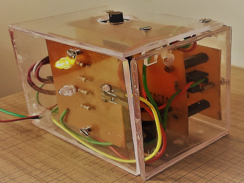
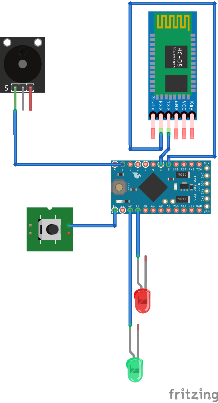
I initially started with an arduino pro mini, HC05 Bluetooth Module etc. using a breadboard with LED and switches. Later I decided to move everything to PCBs designed created by me end to end and also create an acrylic enclosure.
Since I made everything myself - PCB, enclosure etc. I think it would serve as a good guide for individuals who want to try out a project end to end. It would save them efforts of finding the right items and maybe they would come up with better ways of doing things which are always welcome.
I will break this project into the smaller steps which would make it easier to follow and reproduce:
- High level view
- Android Bluetooth Communication
- Arduino Serial Communication
- Breadboard Assembly
- Moving components to PCB
- Enclosure (Acrylic)
Actually the basic principle is quite simple. A communication channel(serial communication) is established between the android device (the phone) and the Bluetooth module(which is connected to the arduino) via an android app. When a call is received by the android phone a particular text is transmitted to the BT device which is read by the arduino. Basis the message the arduino is programmed to execute certain steps. In this case sound the buzzer. A manual reset switch is also given to restore normalcy.
In the reverse operation (panic switch mode) - when the switch is pressed the arduino transmits a given character sequence to the android app. The app on receiving the sequence calls a fixed number already stored in the app.
Android Bluetooth CommunicationThere is this excellent article on Android - Arduino communication by Brian Wirsing which can be found here. I have used the code suggested extensively. Another series of tutorials, which focus more on Android to Android Bluetooth Communication is available as a four part tutorial on you tube. The link to the first part is here.
It is also important to understand the concept of threads and handlers in android. Essentially all code related activities that hold up the user-interface must be put in a separate thread where they can do their work in the background. A handler on the other hand is used to ferry messages between different threads and also interact with the main user interface.
For HC-05 to communicate with an android phone it is necessary that the two be paired and that the HC-05 be the only device that is paired. If your phone has multiple devices paired then unpair all other devices.
Communication between two devices involves :
- setting up a communication path (a.k.a interface)
- Transmitting from one device and receiving in second and vice-versa.
In this project the communication path is set between the Android and the bluetooth device (HC-05 module) . There is also a serial interface between the HC-05 and the Arduino. So in essence the transmission from Android is received by the arduino via the HC-05.
For Android to communicate with the HC-05 the steps involved are:
- Get the BT Adapter - this will also check if blue tooth is supported or not. The getDefaultAdapter() method will return an object of the type BTAdapter if available and supported.
Line 83 of MainActivity.java checks if the adapter is available:
btAdapter = BluetoothAdapter.getDefaultAdapter();
- Get the BT Device - The object BTAdapter has a property getBondedDevices() which will list out all the devices paired with the android phone . If successfully paired our HC-05 module is the first device (remember not to pair any other devices).
Lines 191 and 192 of MainActivity.java return the BTDevice:
btDevice = (BluetoothDevice) (btAdapter.getBondedDevices().toArray())[0];
               btAdapter.getRemoteDevice(String.valueOf(btDevice));
- Open a BT Socket - Once the BTDevice object has been created and the BTAdapter set to the address of the remote device(in our case the HC-05 module), a BT socket is opened between the two (android and BT device). To create a socket we require the UUID () of the remote device.
- HC-05 is a BT device of type SPP (Serial Port Profile) and has a pre-fixed UUID -"00001101-0000-1000-8000-00805F9B34FB". Line 54 of MainActivity.java converts this string to type UUID :
private final UUID MY_UUID = UUID.fromString("00001101-0000-1000-8000-00805f9b34fb");
public void run() {
           try {
               mmSocket = btDevice.createInsecureRfcommSocketToServiceRecord(MY_UUID);
               mmSocket.connect();
           } catch (IOException e) {
               cont = false;
               Message message = Message.obtain();
               message.what = SOCKET_NOT_CONNECTED;
               handler.sendMessage(message);
               e.printStackTrace();
           }
           if ((mmSocket != null) && (cont)) {
               Message message = Message.obtain();
               message.what = SOCKET_OPENED;
               handler.sendMessage(message);
               socket = mmSocket;
           }
       }
   }
- Read and Write using the BT Socket


_t9PF3orMPd.png?auto=compress%2Cformat&w=40&h=40&fit=fillmax&bg=fff&dpr=2)
_3u05Tpwasz.png?auto=compress%2Cformat&w=40&h=40&fit=fillmax&bg=fff&dpr=2)
Comments