For several years, I have wanted to make a mailbox monitoring system, so I wouldn't have to walk out to the mailbox in bad weather, etc., only to find the mailbox was empty! When a boat on a runaway trailer took out my mailbox, I figured the time was right. The reason my mailbox is "sleepy", is that it spends nearly all of it's time in a power-down sleep mode. I have utilized the lowest power sleep mode available, to maximize battery charge life. When no mail is present, mailbox is in sleep mode 100% of the time, and requires an input from interrupt to wake up. When mail is in the mailbox, it wakes up just long enough to flash the status LEDs for 0.1 seconds, check if door is open, and check battery voltage. It then goes back to sleep for 2 seconds, resulting in 94% time in sleep mode when mail is present. Overall, the time spent in power down sleep mode is probably on the order of 98~99%!
Note: as an added feature, if battery voltage falls below 6.2 volts, Status will flash 3 times quickly as mail indication, instead of just once, indicating battery charge needed.
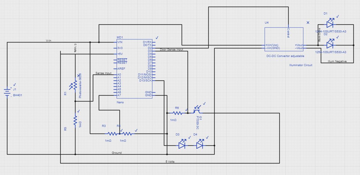
This system uses a photo-transistor to detect door open state on the street side, for when the mail carrier deposits mail. A set of LEDs salvaged from a cheap LED light, and a photo-resistor are used to sense the presence of mail. 2 Red status LEDs mounted on the rear of the mailbox display the presence of mail, and are also used to blink results in any of the 3 test modes incorporated. One allows checking of battery voltage, and the other 2 monitor the photo transistor reading, for calibration and testing.
The Illuminator LEDs are powered by a small adjustable DC-DC converter that is adjusted for the correct brightness for mail detection. The output from the LEDs is intentionally made quite low, as they are extremely bright at full power, which is not needed. This output adjustment is made just by adjusting the output voltage of the DC-DC convertor. The specific converter I chose was selected because it was controlled by a LM2596 adjustable buck regulator IC. Pin 5 of this IC is a control pin, grounding pin turns on converter, pulling this pin high turns it off. I simply unsoldered the control pin (pin 5) of the IC on the DC-DC converter, bent it up so it was not connected to the pad, and wired it directly to the output pin of the Arduino Nano, digital pin 2.
The software incorporates extensive use of the Power Down Sleep Mode, to conserve battery power. If no mail is present, the Arduino enters the power down state, with no timeout, requiring input via interrupt from the photo-transistor door sensor to wake up. Mail presence is checked as follows: When the street side door is closed, testing is initiated, turning the LED illumination inside the mailbox on. The photo-resistor is then checked to see if light is increased from the empty box value. If so, mail is detected, and the status LED blinks once, then Power Down Sleep Mode is entered, with a 2 second timeout, and then the Loop repeats, flashing the LED every 2 seconds. If the rear door is opened, with mail present, the photo-resistor senses the increased light, and initiates the mail check again after the door is closed, to ensure the mail was removed from the box. As an added feature, if battery voltage falls below 6.2 volts, the status indicator will blink 3 times fast, instead of just once, to indicate the presence of mail, and alert the user that battery needs charging.
"You've got mail!" Indication
The test modes are initiated by first putting a piece of paper, etc in mailbox, and closing door, putting it in a mail-present state. The door is then opened again, and the photo RESISTOR covered for about 10 seconds, (while not obstructing the photo transistor) putting the unit into test mode. 1st test mode blinks battery voltage on the LEDs. Other 2 monitor the photo resistor value, one with the LED illumination off, and the other with it on. All test modes timeout after 1 minute, and unit returns to normal operation mode.
Test Mode 1 -Voltage Indication 8.13 Volts
The LED illumination light came from a common LED flip light, available at many locations. I disassembled it, and kept the LEDs and left them attached to the reflector assembly, which became the circuit board mount/LED illuminator. The phototransistor is mounted on the front edge of the reflector, pointing out of the mailbox. The photo resistor is mounted in the middle of the circuit board, which is then mounted on the reflector frame so the photo resistor points down, through the center hole of the reflector.
1 / 4 • Circuit board mounted
Batteries and wiring are all located in the hollow area between top of mailbox interior and exterior. A 3" x 3" access hole was cut near the rear door of the mailbox, on the inside, for battery maintenance/replacement. Eventually, solar charging will be implemented.
#include<LowPower.h>// Library for sleep routines#include<stdio.h>intsensePin=A0;// Photo Resistor Sensor PinintlightPin=2;// LED Illuminator Control PinintdoorPin=3;// Photo Transistor Door Interrupt PinintledPin=13;// Status LED PinintvoltPin=A7;// Battery Voltage Sense PinlonglastCheckMillis=0;// time of last mail check in millislongtestTimeout;// In test mode, returns to normal mode when millis() exceeds this valueconstboolON=LOW;// For controlling Illuminator LEDsconstboolOFF=HIGH;// For controlling Illuminator LEDsvolatileboolboxWasOpened=false;// Set to true when mailbox needs checked for mailinttestMode=0;// Select from mormal run mode (0 value) or a test mode (1 = voltage, 2 = Light sensor, illuminator off, 3 = Light sensor, Illuminator on)boolmailInBox=false;// set to true if mail is detected in boxvoidsetup(){// initialize digital pin LED_BUILTIN as an output.pinMode(LED_BUILTIN,OUTPUT);pinMode(lightPin,OUTPUT);pinMode(doorPin,INPUT);digitalWrite(lightPin,ON);attachInterrupt(digitalPinToInterrupt(doorPin),doorInterrupt,FALLING);// Interrupt for door sensingSerial.begin(115200);Light(OFF);// Start with illuminator off}voiddoorInterrupt(void){boxWasOpened=true;// Ready for mail checking next time through main loopmailInBox=false;}intreadAverage(intmyPin){// Read an average value on any analog pin, 10 iterationsinti=0;intiterations=10;longreadVals=0;for(i=1;i<=iterations;i++){readVals+=analogRead(myPin);}return(readVals/iterations);}voidLight(boolmyStatus){// Control Illuminator LEDsdigitalWrite(lightPin,myStatus);}voidLED(boolmyStatus){// Control Status LEDsdigitalWrite(ledPin,!myStatus);}boolCheckMail(boolhaveMail){// Check for mail in mailbox after door close interruptlongsenseVal;// Photo Transistor value readboolretVal=false;// Return value for functionLight(ON);delay(300);// Allow time for illuminator to stabilizelastCheckMillis=millis();senseVal=readAverage(sensePin);Serial.println(senseVal);if(senseVal>=35){// Mail detected at this light levelretVal=true;}Light(OFF);Serial.println(retVal);returnretVal;}voidwakeUp(){// Just a handler for the pin interrupt.}inttestCheck(void){// check for and initiate test modesif((digitalRead(doorPin)==HIGH)&&readAverage(sensePin)<100){delay(1000);// Only enter test mode if Photoresistor is blocked, door is openedif((digitalRead(doorPin)==HIGH)&&readAverage(sensePin)<100){testMode++;// Increment test mode when command receivedif(testMode>3){testMode=0;Light(OFF);boxWasOpened=true;}Serial.print("Test mode = ");Serial.println(testMode);for(intx=1;x<11;x++){// Indicate test mode selected on the status LEDs before starting test displayflashFast(testMode);delay(500);}testTimeout=millis()+60000;//exit test mode after 60 secondsdelay(1000);}else{}}}voidsleepNow(){// Sleep mode used for NO mail presentif((digitalRead(doorPin)==LOW)&&analogRead(sensePin)<=25){// OK for sleep modeattachInterrupt(0,wakeUp,LOW);//set wakeup interruptSerial.println("Going to sleep now.");delay(200);LowPower.powerDown(SLEEP_FOREVER,ADC_OFF,BOD_OFF);// Set sleep mode NO timeout// Disable external pin interrupt on wake up pin.detachInterrupt(0);Serial.println("Now I'm up!");}else{Serial.println("Not tired yet");}}voidsleep2(){// Sleep mode used for mail IS presentattachInterrupt(0,wakeUp,LOW);Serial.println("Going into sleep2 now.");delay(200);LowPower.powerDown(SLEEP_2S,ADC_OFF,BOD_OFF);// Set sleep mode with 2 second timeout// Disable external pin interrupt on wake up pin.detachInterrupt(0);Serial.println("NOw I'm up!");}voidflash(intiterations){// Flash status LEDs number of times requested in <iterations>for(intx=1;x<=iterations;x++){//digitalWrite(ledPin, HIGH);LED(ON);delay(150);//digitalWrite(ledPin, LOW);LED(OFF);delay(200);}}voidflashFast(intiterations){// double Speed Flash status LEDs number of times requested in <iterations>for(intx=1;x<=iterations;x++){LED(ON);delay(150);LED(OFF);delay(100);}}voidshowSenseRead(intmyVall){// Display Sensor reading on status LEDsintintDigit;StringmyChar;charvalStr[5];sprintf(valStr,"%d",myVall);// Convert reading to a character stringSerial.print("Sensor Value ");Serial.println(valStr);if(myVall==0){// Quickly flash 15 time if reading is zeroflashFast(15);}elseif((myVall>0)&&(myVall<10)){flash(myVall);delay(300);}elseif(myVall>9&&myVall<100){intxVal;xVal=myVall/10;flash(xVal);delay(300);xVal=myVall%10;flash(xVal);delay(300);}elseif(myVall>99&&myVall<1000){intxVal;xVal=myVall/100;flash(xVal);delay(300);xVal=(myVall-xVal*100)/10;flash(xVal);delay(300);xVal=myVall%10;flash(xVal);delay(300);}}voidshowVolts(floatmyVolts){// Display battery voltage on status LEDsintintDigit;if(myVolts==0.00){// Send 0 to force voltage readingmyVolts=readVolts();}myVolts*=1.00;StringmyChar;charvoltStr[6];dtostrf(myVolts,4,2,voltStr);// Convert voltage to a character stringSerial.print("ShowVolts VOltage ");Serial.println(voltStr);// delay(10);dtostrf(myVolts,4,2,voltStr);// Convert voltage to a character stringmyChar=voltStr[0];intDigit=String(myChar).toInt();// Serial.print("Corrent Digit ");//Serial.println(intDigit);flash(intDigit);delay(300);myChar=voltStr[2];intDigit=String(myChar).toInt();//Serial.print("Corrent Digit ");//Serial.println(intDigit);if(intDigit>0){flash(intDigit);delay(300);}else{delay(400);}// mymyChar=voltStr[3];intDigit=String(myChar).toInt();//Serial.print("Corrent Digit ");// Serial.println(intDigit);if(intDigit>0){flash(intDigit);delay(300);}else{delay(400);}}floatreadVolts(void){// Get current battery voltage and return itfloatmyRead;floatmyVolts;myRead=float(readAverage(voltPin));floatmyConv=4.63/1023.00;myVolts=(myRead*2*myConv*1.0811);Serial.println(myVolts);return(myVolts);}voidloop(){staticboollowVolts=false;floatcurVolts;curVolts=readVolts();if(curVolts<=6.5){lowVolts=true;// If battery is running low, LEDs will flasw 3 times, not one for mail indication}testCheck();// Check for test mode requestif((millis()>testTimeout)&&testMode>0){// Return to normal mode after 1 minute of test modetestMode=0;Light(OFF);boxWasOpened=true;// want to ensure check}if(testMode==0){// Normal mail display modeif(digitalRead(doorPin)==HIGH){// Stop mail indication when door is openeddigitalWrite(ledPin,LOW);mailInBox=false;// will be set to true once door is closed}if(readAverage(sensePin>=25)){// Can be due to EITHER door being openedboxWasOpened=true;while(readAverage(sensePin)>=25){//do nothing until door is closed again}}if(boxWasOpened&&digitalRead(doorPin)==LOW){delay(200);if(boxWasOpened&&digitalRead(doorPin)==LOW){//delay(2000);mailInBox=CheckMail(mailInBox);// Actual mail checkboxWasOpened=false;}}Serial.println();Serial.println(mailInBox);Serial.println();if(mailInBox==true){// Mail Present in BoxLED(ON);Serial.println("LED ON");delay(100);LED(OFF);if(lowVolts){// Blink 3 times instead of one for low voltagedelay(200);LED(ON);delay(100);LED(OFF);delay(200);LED(ON);delay(100);LED(OFF);}Serial.println(readAverage(sensePin));//delay(2350);sleep2();}else{LED(OFF);delay(200);sleepNow();// No mail, go to hard sleep }}elseif(testMode==1){// Test mode 1 display// curVolts = readVolts();intmyVall;myVall=readAverage(sensePin);showVolts(curVolts);//flash(5);delay(2000);}elseif(testMode>1){// Test modes 2, 3 displayLight(testMode==2);// light on if testmode is 3intmyVall;myVall=readAverage(sensePin);Serial.print("Light Value ");Serial.println(myVall);showSenseRead(myVall);delay(2000);}}


Comments