

Hardware components | ||||||
 |
| × | 1 | |||
This project is intended to help you get familiar with the QCA4020 System-On-Chip (SoC) Product Development kit. The QCA4020 IoT solution offers Wi-Fi, Bluetooth low energy (BLE), and 802.15.4 capable radios in a single-chip package.The project uses the “Hello world” sample demo included in the SDK with the Eclipse IDE to get started.
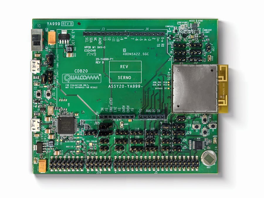
Materials Required / Parts List / ToolsAdditional ResourcesBuild / Assembly InstructionsIn the BoxThe contents of the QCA4020 Development kit, as seen above, include:
- QCA4020 development board
- USB to Micro USB cables
- Power supply
- Jumpers
- Setup guide
For the time being, you can set the kit aside while you install the software components and set up the development environment on your computer. During the setup process, you will only briefly use the kit while installing the FTDI drivers for JTAG.
Set Up the Development EnvironmentInstall Python version 2.7.XSome of the support scripts are Python-based so be sure to install Python 2.7.X because the support scripts do not support Python 3. After installation, add the path to python. Example: If python.exe is in the folder
C:\CRMApps\Apps\Python276-64 set path as follows:%PATH%=%PATH%:C:\CRMApps\Apps\Python276-64
Install Eclipse IDE for C/C++: GUI based integrated development environmentSupported Version: Oxygen version - Release 4.7.2
Install Java: Eclipse IDE has dependency on Java, JDK 8 or higher. After installation, add path to Java. Example: If Java.exe is in
C:\ProgramData\Oracle\Java\javapath set path as follows:%PATH%=%PATH%: C:\Program Files\Java\jdk1.8.0_161\bin
Install OpenOCD version 0.10.0 [2017-06-09] which is available here.OpenOCD plugin is required to establish the connection between Eclipse IDE and onboard FTDI JTAG debugger. After installation, add the path to OpenOCD. Example: If openocd.exe is in
C:\Program Files\OpenOCD-20170609\bin set path as follows:%PATH%=%PATH%:C:\Program Files\OpenOCD-20170609\bin
Download GNU Arm Embedded toolchain version 6.x (gcc-arm-none-eabi-6-2017-q2-update).Install by running the “.exe” file and make sure you select the option to “Add path to environment variables” during the final step.
Set up OpenOCD plugin usage with EclipseInstall GNU MCU plugin for Eclipse
Go to Help > Install new software in Eclipse IDE
In the Available Software window, click “Add” and enter the Name and Location of the repository. Location: “http://gnu-mcu-eclipse.netlify.com/v4-neonupdates” Enter details and click “OK” as seen below.
Select “GNU ARM & RISC-V C/C++ Cross Development Tools” and click “Next” as seen below.
You will see the list of Items to be installed as seen below.click “Next”.
- Follow the steps on screen and select “Finish” to complete the installation.
- Restart the Eclipse IDE
Set path to openOCDRestart the Eclipse IDE and under Window > preferences set path to openOCD as seen below.
Set the Debug Config Go toRun >Debug Configurations > GDB OpenOCD DebuggingSet the Application and OpenOCD options as show in the images below.
Select Quartz.elf as the C/C++ application. If you have already built the image, select Disable auto build. If image is not built, select Use workspace settings.
In the Debugger window, provide the openocd executable path with config option,-f ${project_loc}\build\gcc\qca402x_openocd.cfg
Provide the arm-none-eabi-dgb executable path for the GDB client as seen below.
Download “QCA4020 OEM SDK+CDB” which is available under the Qualcomm Developer Network software section here. The SDK contains sample demo applications with source code to demonstrate different features and technologies that QCA402x supports. Demos are in the following folder:target\quart\demo\
Install the QCA plugin jar file available at<SDK_source>/target/quartz/demo/EclipseSupportFiles
- Copy the jar file (QCA402x_plugin.jar) to the “dropin” folder under the Eclipse IDE installed folder.
- Restart the Eclipse IDE if running. To restart Eclipse, click on the File menu of Eclipse IDE and select the Restart menu item after the plug-in is installed.
Install FTDI driver for JTAG
- Download the zadig application from http://zadig.akeo.ie/.
- Connect the J85 connector on the development board to the host PC using the included Micro-USB cable.
- Once the QCA4020 Development board is connected to the host PC, the Device Manager shows two COM ports. The lower port number is for JTAG and the upper port number is for serial connection.
- Run zadig.exe file and go to
Options > List All devicesand select the device in the drop down. Dual RS232-HS (interface 0) represents lower port number and dual RS232-HS (interface 1) represents higher port number. The following example shows Select Dual RS232-HS (interface 0) to install FTDI on the WinUSB driver for JTAG interface.
After installing the FTDI driver, the Device Manager will look as seen below.
- Make sure that the paths are set correctly under the environment variables.They should be set as seen below.
Congratulations, you have now successfully set up the development environment for the QCA4020 development kit. The next section shows you how to import the sample “Hello World” application.
Import Sample “Hello World” Application- Install Eclipse project files for sample demo applications. To install there is eclipseSupport.bat for Windows and eclipseSupport.sh for Linux in
<SDK_source>/target - Open a terminal window and navigate to
<SDK_source>/target - Run the
“sh eclipseSupport.sh”or“eclipseSupport.bat”command.After executing the script, the Eclipse project files .cproject, .project and .settings folder are updated in the respective folders of the demo applications. - Open the Eclipse application
- Go to
File > Open Projectsfrom File System and set import source for the demo application.Example: <path>/target/quartz/demo/Hello World
You should be able to see the import source as an Eclipse project.
- Click Finish.
Next, build the application.
Build the Application- Go to:
Project properties > Configure buildsetting. - Right click on the project name in project explorer and go to “Properties”.
- Verify the build command and the build directory in the Builder settings tab.
- Go to C/C++ build and set the build command to “build.bat”, and the build directory to “path to source”.
- Click “Apply and Close”.
- Build the application and you will see the following messages in Console Window.
Alright, time to start playing with the Developer Kit.
- Set up the QCA4020 development board as described in Appendix A, “CDB2x board setup” in QCA402x-CDB2x development kit users guide.
- Put the jumper on J31 1&2 on the QCA4020 development board.Tip: There is a “Dot” next to each header that indicates the position of Pin Number 1. After the flashing through JTAG is done, remove the jumper.
- Jumpers on the developer board should be as seen below.Jumper on J31 (Pins 1 and 2), Jumper on J37 (Pins 2 and 3), Cross connect pins 2 and 3 of J38 and J39
- Jumpers on J30 and J32
- Jumpers on J57 and J36
- Open Eclipse IDE and navigate to
Run > External Tools > External Tools Configuration - Click on the program, create a new launch configuration and update the paths as shown below in the Main tab.
- Provide the path for “flash_openocd.bat” or “flash_openocd.sh” in the location box.
- To flash the program, click Run > External Tools > OpenOCD JTAG Flashing The flashing logs can be seen on the Eclipse console.You will see the following lines at the end of the log:
[2018-07-17 16:51:24,434] INFO: Script finished processing generated_fwd_table.xml File:flash_through_gdb.py:699 Function:main
Flash Operation Completed Successfully...
SUCCESS: The process "openocd.exe" with PID 17776 has been terminated.
The application was flashed successfully on the development board.
Run the Application in Autoboot ModeThe Autoboot mode refers to the mode where the system boots up on a power cycle and no JTAG connectivity is required. Follow the below steps to run the application in Autoboot mode.
- Remove the jumper on J31. This was connected to flash the image on the board.
- Power cycle the system.
Once the board powers up, open a serial console on your host PC.Connect it to the com port number assigned to the USB-serial connection with the following settings.
- Baud Rate: 115200
- Data Bits: 8
- Parity: None
- Stop bit: 1
- Flow Control: None
You will see the following stream of text in the terminal window every second.
Hello World demo - Welcome to QCA IoE
Hello World
Hello World
Hello World
Hello World


Comments