The project is about how we can transform complex signal into simple or primary signals. Here we are using audio signal and make them decomposed into signals of different frequencies.
We are using Fourier transform, which helps us to decompose the signal. Fourier analysis converts a signal from its original domain (often time or space) to a representation in the frequency domain.
We are visualizing different frequency bands by their peak at the audio signal. And it can be seen on the 8*8 Led Dot Matrix.
Fourier Analysis has great computational cost, which can't be done on small computers. That's why we will be using Fast Fourier Transform, which is an algorithm that computes Discrete Fourier Transform of a sequence and has less computational cost, can be done on Arduino as well.
Arduino provides a library for Fast Fourier Transform which helps to get our work done more efficiently.
How it works?
Here 3.5mm audio jack delivers signal from computer to the circuit. Then, it is fed to a capacitor rated 10 microfarad, which works as a filter. Then the connection is joined with Arduino analogue input A0, as we will be reading analogue value. Which is later joined with one resistor rated 1k ohms, is connected to the ground(0volts) and, another one, parallel to previous joint, is connected to positive(+5volts) for fixed gain.
The Schematic Diagram of The Circuit
Fig: Circuit Schematic Diagram
For Better Understanding:
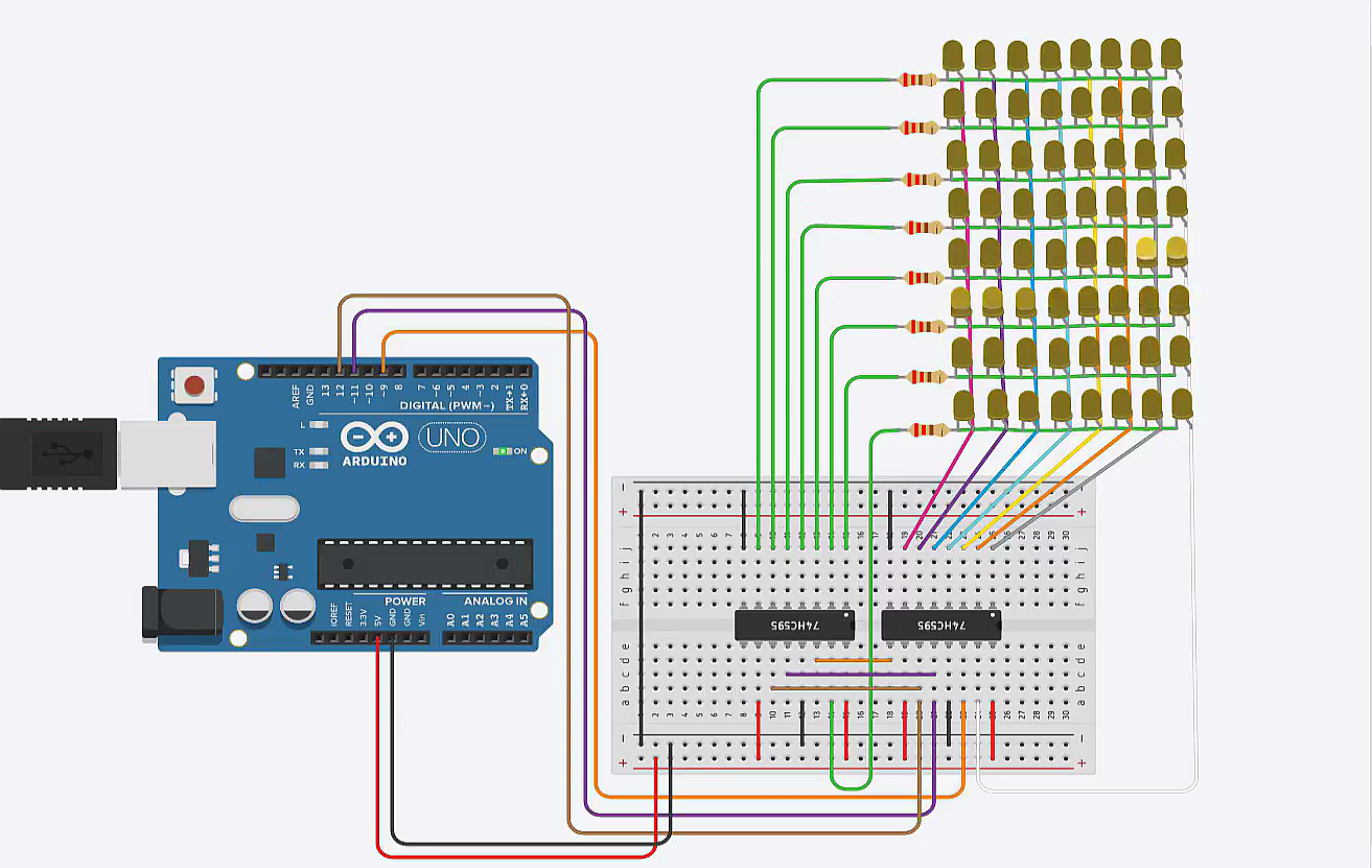
How The LedDot Matrix Works?
How the dot matrix works with hc74595 shift register
Final Outlook of The Circuit
Fig: Final Circuit Outlook
Fig: Final Circuit with Components Label
Full Project Demonstration:
Music Visualizer
Conclusion:
It was a fun experience working with the dot matrix and getting familiar with a new library, which was really exciting. We can also use LCD displays instead of led dot matrix. For large displays, all we need to change is to increase our sampling rate. At the end, It can be a great learning tool too!
#include "fix_fft.h"#define CLOCK 3#define LATCH 4#define DATA 5#define SAMPLES 32 //define according to your need#define AUDIO A0char im[SAMPLES];char data[SAMPLES];int barht[SAMPLES];int binary[]={1, 2, 4, 8, 16, 32, 64, 128};int columnBinary[]={1, 2, 4, 8, 16, 32, 64, 128};void setup(){ pinMode(CLOCK,OUTPUT); pinMode(LATCH,OUTPUT); pinMode(DATA,OUTPUT);}void loop(){ static int i, j; int val; // get audio data
for(i=0; i < SAMPLES; i++){val= analogRead(AUDIO); // 0-1023
data[i]=(char)(val/4 - SAMPLES); // store as char
im[i]=0; // init all as 0} // run FFT
fix_fft(data, im, 5, 0); //2^5=32, as we are taking 32 samples
// extract absolute value of data only, for32 results
for(i=0; i < SAMPLES/2; i++){ barht[i]=(int)sqrt(data[i] * data[i] + im[i] * im[i]);}for(i=0, j=0; i < SAMPLES/2; i++, j+=2){ barht[i]= barht[j] + barht[j + 1];} // display barchart
for(int k=0; k < SAMPLES/4; k++){ //as we have 8rows and 8columns, so only 8times we need to iterate. That's why 32/4=8 .
digitalWrite(LATCH, LOW); int x= columnBinary[barht[k]%8]-1; shiftOut(DATA, CLOCK, LSBFIRST, ~x); // columns
shiftOut(DATA, CLOCK, LSBFIRST, binary[k]); // rows
digitalWrite(LATCH, HIGH);}}
LED matrix test code
Arduino
To test the custom built matrix
byte scroll[]={ 0B11111110,
0B11111101,
0B11111011,
0B11110111,
0B11101111,
0B11011111,
0B10111111,
0B01111111
}; byte point[]={ 0B00000001,
0B00000010,
0B00000100,
0B00001000,
0B00010000,
0B00100000,
0B01000000,
0B10000000
}; int latchPin=11; int clockPin=12; int dataPin=9;void setup(){ // put your setup code here, to run once:
pinMode(latchPin,OUTPUT); pinMode(clockPin,OUTPUT); pinMode(dataPin,OUTPUT);}void loop(){ // put your main code here, to run repeatedly:
for(int i=0;i<8;i++){for(int j=0;j<8;j++){ digitalWrite(latchPin,LOW); shiftOut(dataPin,clockPin,MSBFIRST,scroll[i]); shiftOut(dataPin,clockPin,MSBFIRST,point[j]); digitalWrite(latchPin,HIGH); delay(100);}}}


Comments