

Hardware components | ||||||
 |
| × | 1 | |||
_ztBMuBhMHo.jpg?auto=compress%2Cformat&w=48&h=48&fit=fill&bg=ffffff) |
| × | 1 | |||
 |
| × | 1 | |||
| × | 1 | ||||
| × | 1 | ||||
 |
| × | 1 | |||
 |
| × | 1 | |||
 |
| × | 1 | |||
| × | 1 | ||||
| × | 2 | ||||
| × | 1 | ||||
 |
| × | 1 | |||
 |
| × | 1 | |||
| × | 1 | ||||
| × | 1 | ||||
| × | 1 | ||||
| × | 1 | ||||
 |
| × | 1 | |||
Software apps and online services | ||||||
| ||||||
 |
| |||||
| ||||||
 |
| |||||
| ||||||
| ||||||
Hand tools and fabrication machines | ||||||
| ||||||
 |
| |||||
 |
| |||||
| ||||||
As technology makes rapid strides in all spheres of everyday life, there arises the enduring demand for health-care aids, preventive technologies and monitoring devices that are not only accurate, but also efficient.
Nearly 800,000 people in the United States suffer a stroke every year. Researches have shown that increased temperature tends to increase the risk of a stroke, whereas hypothermia, or reduced temperature, reduces the risk. Of course, the 21st century poses no lack of facilities to battle heat. But throw in financial constrain, and Air Conditioners get ruled out. What's more is that table fans are increasingly difficult to use, as the movement of and the noise from fan blades can lead to headaches.
Talking about bio-sensors and bio-devices, many of them today are implantable, which means that they are embedded inside the body of the subject. Understandably, then, arises the question of powering such devices. The answer: Wireless Charging. The problem then is being able to access their monitored data to track the patient's progress. An important example is that of Pacemakers. As the heat peaks during the summer, our hearts need to work harder to supply adequate oxygen to all body cells. For people relying on Pacemakers, this is a time when they need to be all the more careful.
Another important problem is faced during this part of the year by people who are disabled or partially-paralysed. Patients suffering from developmental disabilities also find their ability to communicate robbed from them. How, then, do they interact with these aids. From very basic functions like raising the fan speed, to more imperative tasks like updating their caregivers as to their conditions, such people need more advanced technologies to help ease their lives.
Solution
This project attempts to solve these problems by invoking the exceptional facilities of the Internet of Things, tapped into using the Onion Omega2 and the Arduino UNO.
The project can be divided into 3 parts:
- Designing a Bladeless Fan to provide seamless cooling to stroke patients
- Imparting Wireless Charging Capabilities to Pacemakers and tracking the readings using IBM Watson
- Building a Communication Aid "Glovvy" for the partially-paralysed that can interface with the Bladeless Fan, and also send SOS messages to caregivers
The standard fans are also hardly as effective as their modern alternatives -- Bladeless Fans. First created by Dyson, bladeless fans have caught the fancy of the masses.
This project instructs the creation of a bladeless fan to help stroke patients combat the heat. Although this won't be as seamless as those commercially produced by Dyson, it comes at a small fraction of the cost.
Working
Bladeless Fans are not entirely "bladeless", and a more accurate connotation is calling them "Air Multipliers".
They possess a tube containing a fan with misaligned wings, that pulls outside air into the tube. This is led into an airfoil-shaped duct within a torus.
Just like the functioning of an airplane, the process creates a difference in air pressures across the fan. This leads to air gushing forward, out of the fan, at a high speed.
In fact, Dyson claims that their fans can pull in up to 5.28 gallons of air per second!
Step 1: Designing the Bladeless Fan
The model is designed on Cinema 4D, although you can also use Autodesk Fusion 360.
The fan has 3 parts -- the tube (with holes for air flow) that holds the fan, an outer torus into which the tube slides, and an inner torus that fits into the outer one while leaving a duct for air flow.
Make sure to accurately measure the dimension of the fan and construct the tube accordingly.
Step 2: Printing
Print the parts, preferably on a hot bed. The simple design should give minimal problem, and once done, ensure that the parts slide in and out of their designed cavities with ease.
Step 3: Preparing the Fan
The recycled computer fan probably has a rectangular case bordering the fan. Unscrew this case and expose the fan. Now fit the fan base-first inside the printed tube.
After ensuring that the fan blades can rotate freely inside the tube, secure the fan using a hot glue gun.
Step 4: Connect the Fan to the Omega2+
Connect the PWM Expansion to the Dock. Now make the following setup:
- The red wire of the fan is connected to the VCC
- The black wire of the fan is connected to the transistor's collector
- Connect the transistor's base to the PWM Expansions's SIGNAL pin through a resistor
- Ground the transistor's emitter
- Connect a capacitor across the fan's terminals
Step 5: Temperature Sensing
The DS18B20 has 3 pins. Connect it in the following way:
- Connect its VDD to a 3.3V pin on the Expansion
- Connect its DQ to GP101
- Connect it GND to the Expansion's Ground
- Connect the VDD and DQ pins through a 5.1kΩ resistor
Step 6: The Code
Now we use code to bring the electronics to life. We use a Python script, which uses web request to get weather data of the region, especially the temperature. We also read the user's body temperature through the temperature sensor.
For a considerable difference in the body temperature vis-a-vis the environment temperature, the fan runs at a speed proportional to the difference, thereby creating an air conditioning effect.
Part 2: Monitoring the Data from a Pacemaker, made wirelessPacemakers are used to control abnormal heart-beating rhythms. They are implanted in the chest or abdomen.
Wireless Charging would improve the life of the device, thereby reducing the need for replacing the existing device, which not only poses a risk due to surgery, but also creates additional bio-waste. Keeping the battery of the device fully charged would also result in an increased efficiency of the device.
Apart from attempting this, we will also monitor the data logged by the pacemaker using IBM Watson's IoT interface Bluemix.
How a Pacemaker Works
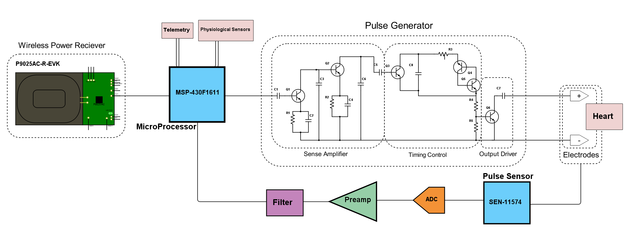
We deal with a Demand Pacemaker, which provides electrical heart-stimulating pulses only in the absence of natural heartbeat. When it was introduced in 1964, the Demand Pacemaker offered significant advantage over the previously-used pacing devices, which delivered a fixed-rate pulse, thus competing with natural heartbeat and sometimes inducing ventricular fibrillation. The Demand Pacemaker also prolongs battery life because it is only activated when pacing stimuli are needed.
The Demand Pacemaker, connected to the IDT Wireless Power Receiver Board P9025AC-R-EVK, is shown in Schematic Form.
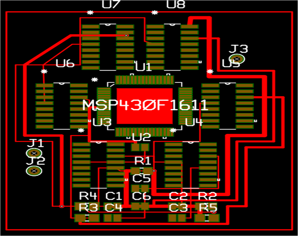
The Pacemaker's PCB Layout is shown.
Note that junctions J1 and J2 connect to the terminals of the P9025AC-R-EVK Receiver board, while the junction J3 leads to the electrodes implanted in the heart.
The Sense Amplifier amplifies and normalizes the cardiac signal. It lets out undesired signals like the P and T waves and 60 Hz stray signals. Q1 and Q2 are Class A amplifiers. AC signals at the collector of Q2 are coupled with capacitor C8 to momentarily turn on Q3, which is the Timing Capcitor (C8) discharge switch.
The Sense Amplifier incorporates a bandpass filter with a bandwidth of 20-30 Hz that limits the low frequency response of the detecting circuit to discriminate against the P and T waves and any other frequencies below 20 Hz.
When the Pacemaker is required to operate in demand mode, each pulse transmitted through capacitor C5 to the base of transistor Q3 causes the transistor to conduct. Capacitor C8 discharges through the collector–emitter circuit of the transistor. In this case, the timing cycle is interrupted and the junction of capacitor C8 and resistor R3 does not increase in potential to the point where transistors Q4 and Q5 are triggered to conduction. After capacitor C8 discharges through transistor Q3, the transistor turns off. The capacitor then starts charging once again and the new cycle begins immediately after the occurrence of the last heartbeat.
Making a Pacemaker Wireless
Since a Pacemaker is not easily available (a condemned machine is officially a bio-hazard) and is fairly expensive, we recreate here the most integral component of a Pacemaker: its Pulse Generating Circuit.
A pulse generating circuit has to deliver electrical pulses at regular intervals of time. Such a circuit can be created as follows.
Step 1: Ready your Supplies!
What you'll need for this is an NE 555 made by Texas Instruments, an LED bulb, a 0.01 μF Capacitor, a 10 μF Capacitor, a 330 Ω Resistor, a 270 kΩ Resistor, a 33 kΩ Resistor, a breadboard and plenty of jumper wires. You'll also need a power source, which includes the IDT P9038-R-EVK - Qi 5W Transmitter and the IDT P9025AC-R-EVK - Qi 5W Receiver.
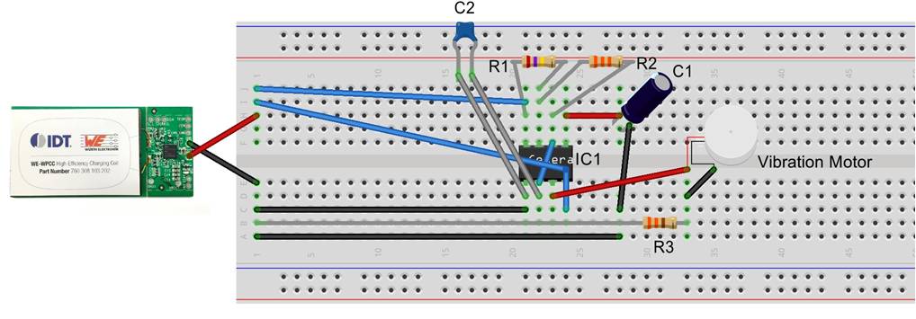
Step 2: Ready the Working Circuit
Connect the NE 555 to the breadboard. Note the orientation of the small IC using the notch at the top.
(A) NE 555 IC and Receiver Board
Connect the Receiver board's OUT point to the NE 555's Power (8) and Reset (4) pins. Connect the Receiver's GND- terminal to the NE 555's Ground (1). Now connect the 0.01 μF Capacitor between the Ground (1) and Trigger (2) pins of the NE 555. This helps in regulating power flow into the IC and the initiation of the circuit.
(B) Resistors
Now connect the 270 kΩ Resistor between the +VCC (8) and Discharge (7) pins and the 33 kΩ Resistor between the Discharge (7) and Threshold (6) pins. Since I only had 90 kΩ and 22 kΩ resistors, I connected 3 90 kΩ resistors in series and a parallel combination of two 22 kΩ resistors in series with another 22 kΩ resistor to get the desired resistances.
(C) Capacitor
Next take the 10 μF capacitor; connect its positive terminal to the NE 555's Control Voltage (5) point and its negative terminal to the power sources ground terminal.
(D) LED Bulb
On this connection, attach a 330 Ω resistor which is connected to the negative terminal of the LED bulb. Connect the bulb's positive terminal to the NE 555's Output (3) pin.
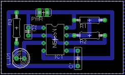
The PCB design of the Pulse Generating Circuit is shown for reference.
Note that the magnitudes (values) of C1, R1 and R2 need to be chosen according to the time period of periodicity of the pulse (or equivalently its frequency). Get a conversion chart here.
Step 3: Ready the Powering Mechanism
Now get hold of the amazing Transmitter Board, and plug it in through its Mini USB. As current flutters in through its coil, a green and a red light should come to life atop the board. Now take the Receiver Board close to the Transmitter. At the correct relative orientation of and distance between the two boards, an induction current would be set on in the Receiver's coil, thereby lighting an LED on board. To test this or learn more, see this. Note that the green light on the Transmitter begins to blink and the red light goes off. Phew!
Your LED in the pulsating circuit should now begin to blink.
A device that closely matches the functioning of a pacemaker and heart is a vibration motor, which can be operated using the Pulse Generating Circuit in place of the LED.
The SparkFun Vibration Motor used here vibrates periodically with a time period of 2 seconds given the resistances and capacitance used.
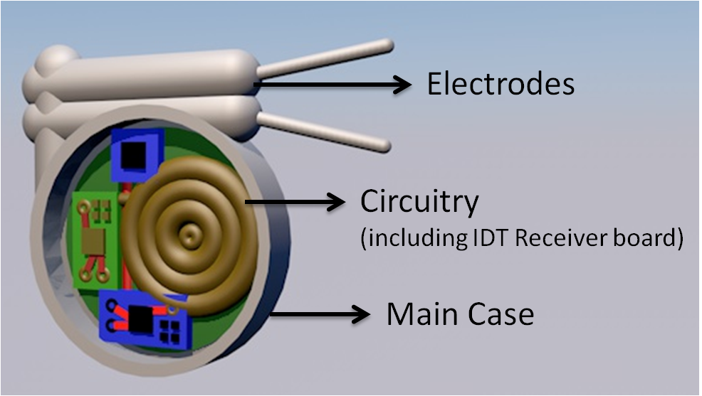
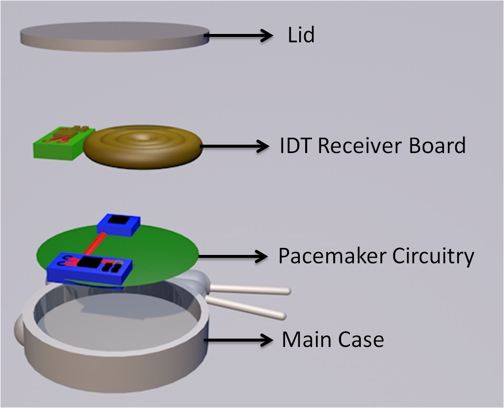
Step 4: Packing the Pacemaker
The Pacemaker is enclosed in a hermetically sealed case. A 3D Model of the Pacemaker and how the various components fit in is given below.
Earlier, the pacemaker needed to be replaced surgically when the battery run out. With wireless charging, the painstaking and risky process is no longer required!
Step 5: Testing
In order to test the working of the system, take the Pulse Generator (with LED) and fasten it inside your shirt. Make sure to keep the back side of the Receiver board PCB away from the body. If the board is kept the other way around, then the insulating sticker on top of the receiver coil would prevent any induction from occurring.
Now connect the Transmitter board to a power source and bring it close to the circuit. Recall the correct orientation of the two coils that we had studied earlier. When the coils are placed correctly, the LED should blink.
Step 6: Monitoring the Data
The values of vibration frequency of the pulse generating circuit can be tracked using IBM Watson.
In order to setup an IoT Platform Organisation (the first step if you are new), refer to the instructions here.
Once you are done, you will have your device ready. Now you can build cards -- charts that will display the data that your device sends to Watson. This is a way of analysing the data without any programming.
You can also use conditional constructs to send alerts. These are called actions. Go ahead and add an action to send an Emergency Alert in case the vibration values cross a certain threshold.
Over 100 million people in the world cannot speak because of a developmental disability or a speech-related disorder. Such people rely on technological developments that enable them to lead normal lives.
Glovvy is an aid to allow the partially-paralysed to utilize hand or feet movements in order to communicate. Particular series of movements are translated into specific words or requirements, which can be expressed seamlessly with Glovvy.
The Flex Sensors
Glovvy consists of flex resistors whose resistance varies as the flex resistance is bent. The Flex Sensor technology is based on resistive carbon elements. As a variable printed resistor, the Flex Sensor achieves great form-factor on a thin flexible substrate. When the substrate is bent, the sensor produces a resistance output correlated to the bend radius—the smaller the radius, the higher the resistance value.
The basic circuit consists of a fixed resistor in series with a variable resistor (Flex sensor) causing the voltage between the two to vary when a fix voltage is given to the combination. The flex sensor/resistance acts as a voltage divider and causes V(out) to vary as the same is bent. V(out) is detected and converted to a digital value, which then displays the information/message that the patient wants to convey according to the following table.
The LCD
LCDs have a parallel interface, so the microcontroller has to manipulate several interface pins at once to control the display. The interface consists of the following pins:
- A register select (RS) pin that controls where in the LCD's memory we're writing data to. We can select either the data register, which holds what goes on the screen, or an instruction register, which is where the LCD's controller looks for instructions on what to do next.
- A Read/Write (R/W) pin that selects reading mode or writing mode
- An Enable pin that enables writing to the registers
- 8 data pins (D0 -D7). The states of these pins (high or low) are the bits that we're writing to a register when we write, or the values we're reading when we read.
There's also a display constrast pin (Vo), power supply pins (+5V and Gnd) and LED Backlight (Bklt+ and BKlt-) pins that we can use to power the LCD, control the display contrast, and turn on and off the LED backlight, respectively.
The process of controlling the display involves input of image forming data into the data registers, and further input of instructions to the instruction register. The Liquid Crystal Library simplifies this for us so we don't need to know the low-level instructions.
The Hitachi-compatible LCD used in my case can be controlled in two modes: 4-bit or 8-bit. The 4-bit mode requires seven I/O pins from the Arduino, while the 8-bit mode requires 11 pins. For displaying text on the screen, we can do almost everything in 4-bit mode.
Step 1: Flex Sensors
The flex sensors are mounted in a glove worn by the patient. Two flex sensors are attached to the index and the middle fingers of the glove.
Each sensor is connected in series with a 1K resistance. Each combination of flex sensor and 1K resistor is connected to a DC power source. Each of these then give input to the Arduino at A0 and A2 pins.
Step 2: LCD
The microcontroller is given +5V Power and the ground pin of the same is connected to Ground. The digital-out from the Arduino (Pins no. D8-D12) is fed to the digital-in (Pins DB4-DB7) of the LCD.
The 'LED -' pin of LCD is grounded and 'LED +' Pin of the LCD is given +5V. The Rx and Tx of the GSM module are connected to the Tx and Rx of the microcontroller respectively.
A potentiometer (10K) is attached in series with the LCD Pin V(ee) to control the brightness of the LCD (Back light brightness).
Step 3: Code
Note that this process involves understanding the flex sensors, because different sensors return different values when bent to the same level.
The Arduino IDE is used to program the microcontroller which then displays the particular message for a particular range of V(out) on the LCD. At the same time, a message is sent to a predefined mobile number to the attendant in case of an emergency message. Otherwise, this is used to vary the speed of the bladeless fan.
As the flex sensor is bent, the resistance of the flex sensor is changes. Thus if a constant voltage is applied to the combination of a fixed resistance (1K) and the flex sensor, as the sensor bends the total resistance of the combination keeps on changing thereby changing the voltage at the junction between the two resistors. A particular voltage at the analogue pins of the Arduino will result in a particular binary code in the internal registers of the microcontroller. In the software code, a particular range of this binary code is assigned to a pre-defined output displayed on the LCD, e.g. when the V(out) is half of V(in) on bending the flex sensor, the LCD displays “Increasing Speed”, and the corresponding message is passed to the Omega2.
The patient is expected to bend his/her finger(s), keeping them either half-bent or fully-bent. Thus for each finger there will be two resistance values which are cnsidered in the project. For this prototype, I programmed for the fully-bent state of each finger. I also utilized the event when the patient will bend more than one finger at any given time (for example clinching the fist). The three events were then programmed to mean -- increase speed, decrease speed and emergency. It may be noted that using 5 sensors, 31 events can be programmed considering only one bent state for each finger.
Thus we have achieved our engineering goals. We have built a communication aid for the partially-paralysed that utilises an Arduino docked to the Omega2. It can also alter the speed of a unique Bladeless Fan that we built to help stroke patients battle the heat. The fan otherwise uses web requests to calculate the region's temperature, compares it with the user's body temperature, and conditions the air accordingly. We also took an essential implantable bio-device -- the pacemaker -- and added wireless charging capabilities to it. We also used the IBM Watson IoT Interface to wirelessly track the number of vibrations the pacemaker needed to make to supplement the heart's natural rhythms, so that the patient's condition can be monitored regularly and seamlessly.
If you have followed through and completed the entire project, heartiest congratulations! The essential condition to be a good samaritan is to use one's own skills for the benefit of others. And by completing this project, you have created a combination of three aids that hold the potential to greatly improve the lives of those who rely on aids to lead equal lives.
AcknowledgementThe Omega2+ Project Book (Vol. 1) is an excellent resource to learn more about using the wonderful computer-on-a-chip and helped me through this project! A must read for Omega2+ developers.
The IBM Developer recipes are extensive in their dealings of IBM Watson and were of great help.
Occasionally throughout the project, forums and communities like Hackster, StackOverflow and Instructables proved to be of great help in debugging.

Pulse Generating Circuit with Vibration Motor


_t9PF3orMPd.png?auto=compress%2Cformat&w=40&h=40&fit=fillmax&bg=fff&dpr=2)


_3u05Tpwasz.png?auto=compress%2Cformat&w=40&h=40&fit=fillmax&bg=fff&dpr=2)

Comments