


Hardware components | ||||||
| × | 1 | ||||
| × | 1 | ||||
 |
| × | 1 | |||
 |
| × | 1 | |||
 |
| × | 1 | |||
 |
| × | 1 | |||
 |
| × | 1 | |||
| × | 1 | ||||
Software apps and online services | ||||||
 |
| |||||
Water tank overflow is a common household issue that results in water wastage. An efficient solution to this problem is a water level monitoring system using a water level sensor and an Arduino. This system helps monitor the water level in the tank and alerts users or triggers an action to stop the overflow.
In this tutorial, we will explore how water level sensor work, how to interface it with an Arduino, and how to create a water level indicator that activates an LED and buzzer when the water exceeds a certain level.
How Does a Water Level Sensor Work?A water level sensor operates by detecting the level of water in a container or tank. The sensor has conductive traces, and its functionality is based on the change in resistance caused by the water’s conductivity.
- Increased Water Level: As more of the sensor gets submerged, the conductivity improves, and the resistance decreases.
- Decreased Water Level: With less of the sensor submerged, the conductivity diminishes, and the resistance increases.
This change in resistance is converted into an analog voltage output that varies with the water level. By measuring this voltage, you can accurately determine the water level.
Key Specifications of the Water Level Sensor- Operating Voltage: 3–5V (< 20m)
- Humidity Range: 10%–90% (non-condensing)
- Operating Temperature: 10°C–30°C
- Sensor Type: Analog
- Output Voltage Range: 0–3.85V
- Detection Area: 40mm (height) x 16mm (width)
The water level sensor has three pins:
VCC: Supplies power to the sensor.
GND: Ground connection.
OUT: Analog output pin that provides signals proportional to the water level.
Wiring the Water Level Sensor to ArduinoAttach the sensor’s VCC and GND pins to the 5V and GND pins of the Arduino, respectively. Connect the sensor’s OUT pin to an analog input pin A0 on the Arduino. Link the SCK and SDA pins of the LCD to the I2C pins on the Arduino. Connect the LCD’s VCC and GND to the Arduino’s 5V and GND pins. Then connect Vcc and Ground to the Vcc and Ground pins of Arduino and sensor.
Arduino Code/*
Interfacing Water Level Sensor with Arduino UNO using Analog Output pin of Module
by www.playwithcircuit.com
Using this code we will know the Analog Value when water level is very low and when it is very high.
*/
#include <LiquidCrystal_I2C.h> // Library to Run I2C LCD
// define the size of filter array
#define FILTER_SIZE 20
// Set the LCD address to 0x27 for a 16 chars and 2 line display
LiquidCrystal_I2C lcd(0x27, 16, 2);
// Define the analog pin for the soil moisture sensor
const int WaterSensorPin = A0;
// Analog Value filter
int Filter(int sensorValue);
void setup() {
// initialize the lcd
lcd.init();
// Turn on the Backlight
lcd.backlight();
// Clear the display buffer
lcd.clear();
// Print a message to the LCD
lcd.setCursor(0, 0);
lcd.print("Analog Value:");
}
void loop() {
// Variable to store sensor values
int sensorValue;
// Variable to store filtered values
int filteredValue;
// Read the value from the soil moisture sensor
sensorValue = analogRead(WaterSensorPin);
filteredValue = Filter(sensorValue);
// Display the filtered Analog Value on the LCD
lcd.setCursor(0, 1);
lcd.print(filteredValue);
// Clear Previous Data
lcd.print(" ");
// Wait for 50ms before the next loop
delay(50);
}
// Averaging filter to filter Analog Values
int Filter(int sensorValue) {
static int analogArray[FILTER_SIZE] = { 0 };
int filteredValue = 0;
int i;
// Shift the Elemnent removing the oldest value stored at index 0
for (i = 0; i < (FILTER_SIZE - 1); i++) {
analogArray[i] = analogArray[i + 1];
}
// Put the current value in the last element of Array i.e at index FILTER_SIZE-1
analogArray[FILTER_SIZE-1] = sensorValue;
for (i = 0; i < FILTER_SIZE; i++) {
filteredValue += analogArray[i];
}
// Return Filtered Analog Value
return (filteredValue / FILTER_SIZE);
}In this project, we’ll design a simple yet effective water level indicator system using an Arduino, a water level sensor, an RGB LED, an LCD display, and a buzzer. This system will monitor the water level in a container, display the level on the LCD as a percentage, and provide visual and audible alerts to prevent overfilling.
How It WorksThe water level sensor measures the water level inside the container and sends the data to the Arduino. The Arduino then processes the data and performs the following actions:
RGB LED Indication:
- Low Water Level (<10%): The RGB LED lights up red, signaling the container needs more water.
- Medium Water Level (10%–99%): The RGB LED lights up blue, indicating the water level is acceptable but not full.
- High Water Level (≥99%): The RGB LED lights up green, signaling that the container is full. The buzzer is activated to alert you to stop filling.
LCD Display:The LCD shows the water level as a percentage.
- 0%: Represents an empty container.
- 100%: Indicates full container
When the water level reaches 99% or higher, the buzzer sounds.
Wiring DiagramTo learn how to Calibrate Water Level Sensor and step by step explanation check out: Water Level Sensor with Arduino
Project Demonstration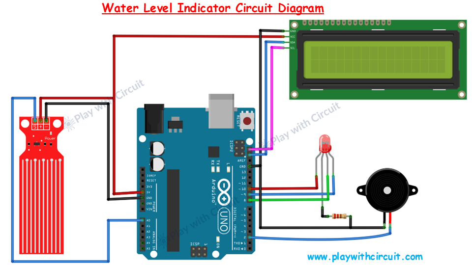


Comments