


Hardware components | ||||||
 |
| × | 1 | |||
 |
| × | 1 | |||
 |
| × | 1 | |||
 |
| × | 1 | |||
Software apps and online services | ||||||
 |
| |||||
 |
| |||||
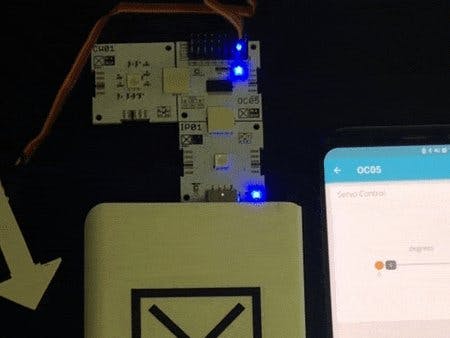
The xChip OC05 talks to CW01 using I2C protocol. OC05 has 8 PWM channels. OC05 uses PCA9685 PWM controller to control servo motors using Pulse Width Modulation. Servo motors are powered through external battery which is then regulated using BU33SD5 regulator. With CW01 attached to OC05, CW01 gets data and processes to set PWM to control position of servo motors.
By the end of this guide, you will able to control servo motors remotely using ubidots and Xinabox xChips IP01, CW01 and OC05.
Requirements- 1x CW01 - WiFi core (ESP8266/ESP-12F)
- 1x OC05 - Servo Driver (PCA9685 & BU33SD5)
- 1x IP01 - USB Programming Interface (FT232R)
- 1x XC10 - 10-Pack xBUS Connectors
- Arduino IDE
- Ubidots account
1. Hardware Setup
2. Setting up the Arduino IDE
3. Create Slider Widget
4. Coding
5. Compile and Upload from Arduino IDE
6. Summary
Step 1: Hardware Setup1. Connect CW01, OC05 and IP01 together using the XC10 xBUS connectors. You may connect it as shown in the diagram below. Please see this guide on how to assemble xChips generally.
Then, connect your device and PC through the IP01’s USB. Your servo can be connected to one of the 8 headers on the OC05.
Step 2: Setting Up the Arduino IDE1. Install Arduino IDE 1.8.8.
2. Install these libraries/cores to Arduino:
NOTE: If you are not familiar with how to install libraries, please refer to the link: Installing Arduino libraries
3. With the ESP8266platform installed, select the ESP8266 device you are working with. In the case, we are working with a “CW01”. To select your board from the Arduino IDE, select Tools > Board “XinaBox CW01”.
Step 3: Create Slider Widget1. Login to your Ubidots account:
2. Create a new device. To create a new device, click the "+" icon in the top right corner of the Device's section of your account. Then, assign “OC05” device name:
Once the device is created it will be appear listed in the device section:
3. Enter to the device created and add a new raw variable by pressing the "+" icon. The variable ought to be called “degrees”:
Once the variable is created you should have the following result:
IMPORTANT NOTE: In order to be able to establish the communication, the Device & Variable label assigned in the platform should be the same assigned in the code. To learn more about Devices & Variable Labels, refer to the following article.
4. Go to the dashboard ("Data > Dashboards") section to create a new control widget. To create a new control widget into the Dashboard click on the “+” icon in the top-right corner of the dashboard user interface. Then, select "Slider" as widget type and assign the device and variable previously created.
Set minimum value to “0” and maximum to “180” degrees. Enter Step size to 1:
Once the widget is created, you should have the following result:
Defining constants:
#define SERVO_MAX 450 //servomotor maximum PWM
#define SERVO_MIN 130 //servomotor minimum PWM
#define SERVO_CHANNEL 1 //Enabling only channel 1
Including libraries:
#include "UbidotsMicroESP8266.h"
#include <xOC05.h>
#include <xCore.h>
Enter your Wi-Fi Credentials and Ubidots TOKEN where indicated:
#define DEVICE “OC05” // Put here your Ubidots device label
#define VARIABLE “degrees” // Put here your Ubidots variable label
#define TOKEN “your-ubidots-token” // Put here your Ubidots TOKEN
#define WIFISSID “your-accesspoint-ssid” // Put here your Wi-Fi SSID
#define PASSWORD “your-accesspoint-password” // Put here your Wi-Fi password
IMPORTANT NOTE: You can choose your own Device and Variable Label, but labels of both should be assigned respectively.
One time setup, see the comments for self-explanation:
void setup() {
    value=0; //Current slider value
    prevValue=0; //Previous slider value
    //Serial.begin(115200); //Enable it for serial debugging
    client.wifiConnection(WIFISSID, PASSWORD); //Establis Wi-Fi
    //connection with access point
    Wire.begin(); //Begin I2C communication
    OC05.begin(); //Begins with default I2C Addr. 0x78
    OC05.setPWMFreq(60); //Set PWM frequency to 60Hz
    //client.setDebug(true); // Uncomment this line to set
    //Wi-Fi DEBUG on
}
Loop operation, keeps running and updating again and again
void loop() {
   //Getting slider value
    float value = client.getValueWithDevice(DEVICE, VARIABLE);
    //Mapping degrees(0-180) to servomotor PWM range
    value= map(value,0,180,SERVO_MIN,SERVO_MAX);
    //Checking whether slider value changed
    if(prevValue!=value){
      OC05.setPWM(SERVO_CHANNEL,value);
      prevValue=value;
    }
    delay(500);
}
The Complete Code, please read the comments:
#include "UbidotsMicroESP8266.h"
#include <xOC05.h>
#include <xCore.h>
#define SERVO_MAX 450 //servomotor maximum PWM
#define SERVO_MIN 130 //servomotor minimum PWM
#define SERVO_CHANNEL 1 //Enabling only channel 1
#define DEVICE "OC05" // Put here your Ubidots device label
#define VARIABLE "degrees" // Put here your Ubidots variable label
#define TOKEN "your-ubidots-token" // Put here your Ubidots TOKEN
#define WIFISSID "your-accesspoint-ssid" // Put here your Wi-Fi SSID
#define PASSWORD "your-accesspoint-password" // Put here your Wi-Fi password
xOC05 OC05; //Creating OC05 object
Ubidots client(TOKEN); //Creating ubidots client
float value,prevValue; //Declaring variables to store current and past //values
void setup() {
    value=0; //Current slider value
    prevValue=0; //Previous slider value
    //Serial.begin(115200); //Enable it for serial debugging
    client.wifiConnection(WIFISSID, PASSWORD);//Establish Wi-Fi
    //connection with access point
    Wire.begin(); //Begin I2C communication
    OC05.begin(); //Begins with default I2C Addr. 0x78
    OC05.setPWMFreq(60); //Set PWM frequency to 60Hz
    //client.setDebug(true); // Uncomment this line to set
    //Wi-Fi DEBUG on
}

void loop() {
    //Getting slider value
    float value = client.getValueWithDevice(DEVICE, VARIABLE);
    //Mapping degrees(0-180) to servomotor PWM range
    value= map(value,0,180,SERVO_MIN,SERVO_MAX);
    //Checking whether slider value changed
    if(prevValue!=value) {
      OC05.setPWM(SERVO_CHANNEL,value);
      prevValue=value;
    }
    delay(500);
}
1. You will now use Arduino IDE to Compile and then Upload the code to the CW01, having made sure you have selected CW01 board, and connected on the correct USB port.
2. In the Ubidots Dashboard the OC05 can be controlled with the slider widget that was added. When you slide, servomotor rotates to that specific position.
In this tutorial, we have shown how to control servo motors using XinaBox xChips CW01/OC05/IP01 with Ubidots remotely from anywhere. With XinaBox and Ubidots you can now control doors and windows from anywhere to automate your home. The project is fairly simple, and may take up to 15-20 minutes.
Other readers have also found useful...


Comments