


Hardware components | ||||||
| × | 1 | ||||
 |
| × | 1 | |||
Software apps and online services | ||||||
| ||||||
 |
| |||||
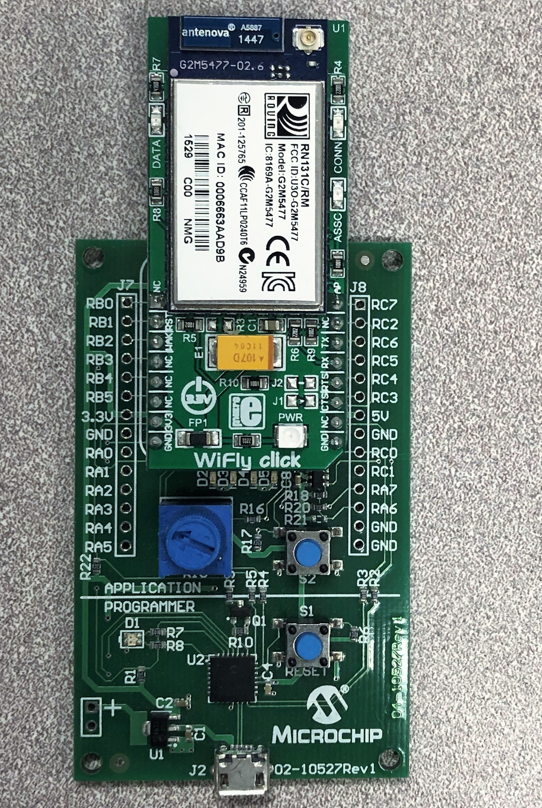
We will connect the WiFly Click board to the MPLAB Xpress Evaluation Board and use MPLAB Xpress Code Configurator (MCC) to configure the Click in software.
Then, on a PC, we will host a server by creating a Python socket. To demonstrate and test the connection, we will use the Python socket to communicate with the WiFly module.
Note: It may be difficult to create an IoT node on a shared network, such as at your company or university. I connect both my PC and my WiFly module to a hotspot on my phone to create a private network.
Easily import this code by viewing the MPLAB Xpress example.
Step 1 - Open New ProjectCreate a new "Stand-Alone" project in MPLAB® Xpress for a PIC16F18855 using the MPLAB Xpress Evaluation Board. If you are not sure how to do this, check out the tutorial here.
Step 2 - Open MCCOpen the MPLAB® Code Configurator using the blue shield link on the toolbar. You can find information on how to open MCC here.
Step 3 - Set Up WiFly ClickUnderneath Device Resources, scroll to the bottom of the menu to find and click Mikro-E Clicks.
Choose Wireless Connectivity and then click on WiFly to open the WiFly click window.
The important tab to note here is the Notifications tab which will inform you if there are any special programming requirements of the WiFly click.
From the Notifications tab we can see the only severe warnings are to set up the pins, therefore it is time to move on to the pin manager.
The notifications tell us that the important pins to set up for the WiFly click are the Hardware Reset Pin and the Wake Pin.
The Hardware Reset Pin is connected to pin RB1 on the PIC16F18855 while the Wake Pin is connected to pin RB2.
When you chose the WiFly click in MCC, the Foundation Services Libraries also auto-generated a EUSART(Enhanced UART) module because the RN131C/RM Wifi Module on the WiFly click communicates with the PIC16F18855 microcontroller over UART serial communication.
The pins for the EUSART communication also need to be configured in the pin manager. The TX of the PIC connects to the RX of the click, so select RX in the pin manager to connect to RC6. Similarly, connect the TX in the pin manager to pin RC5, the pin connected to the RX of the click.
If you are using the same connections as myself, then your pin manager grid view should look like the one below:
The package view will look like the following:
We also need to update the EUSART module to allow the PIC microcontroller to send and receive UART communication.
Underneath Project Resources scroll to the Peripherals tab and double click EUSART to open it. Make sure that both the Enable Transmit and Enable Receive check boxes are checked.
Once you are finished configuring the pins, click Generate in the upper left-hand side of the MCC window and return to the MPLAB Xpress IDE window.
Step 4 - WiFly Code ExampleLook at the MCC generated filesAfter you hit “Generate” in MCC in step 3, program files were imported into your code in MPLAB Xpress.
MCC automatically added source and header files for an example as well. Look through EXAMPLE_WiFly.h to see the three WiFly functions that work together to enable communication over WiFi in our example.
You will just use the example for this tutorial, but you should still look through the files to become familiar with functions you’ll be using when you start prototyping with the WiFly Click.
Troubleshooting: If you are using an older version of MCC, you may need to modify the example function. Under EXAMPLE_WiFly.c change the function:void WiFly_Example_Connect(const char addr, const char port) and deleteinCmd = 0;
void WiFly_Example_Connect(const char* addr, const char* port) {
WiFly_SendCMD_DoubleArg("open %s %s\r\n", addr, port);
WiFly_CheckRecv(openStr);
}
Navigate to the main.c file and include the Example_WiFly.h header file.
#include "mcc_generated_files/mcc.h"#include "mcc_generated_files/EXAMPLE_WiFly.h"
We will enable interrupts and initialize our WiFi setup inside the main loop, but before the while (1) loop.
We need to be able to interrupt the MCU to communicate with the WiFly. To enable interrupts, uncomment the INTERRUPT_GlobalInterruptEnable() and the INTERRUPT_PeripheralInterruptEnable() functions.
// initialize the device
SYSTEM_Initialize();
// Enable the Global Interrupts
INTERRUPT_GlobalInterruptEnable();
// Enable the Peripheral Interrupts
INTERRUPT_PeripheralInterruptEnable();
// Disable the Global Interrupts
//INTERRUPT_GlobalInterruptDisable();
// Disable the Peripheral Interrupts
//INTERRUPT_PeripheralInterruptDisable();
We will also initialize the WiFi setup before the while (1) loop. The two functions we will use to initialize WiFi are:WiFly_Example_InitializeAsClient(const char* ssid, const char* password) andWiFly_Example_Connect(const char* addr, const char* port)
WiFly_Example_InitializeAsClient tells the WiFi module which network it will become a client of. You will have to insert the ssid (network name) and password of the network you would like to connect to.
I used a network that was named "Microchip" with a password also named "microchip".
I replaced const char* ssid with "Microchip" and const char* password with "microchip"
WiFly_Example_InitializeAsClient("Microchip", "microchip");
The 'WiFly_Example_Connec't function tells the WiFi Module what the IPV4 address of the device on the network it will be connecting to is, as well as the port on that device.
Microchip has provided example code to create a basic Python server to facilitate the connection between your PC and your PIC MCU. I use a program called IDLE to run Python scripts on my computer, but any program that can run Python scripts should work.
This example code defines the port we will use in this tutorial as "1337". You can find the code to create the server on Github.
The IPV4 address will be specific to your network and device, but an easy way to check, if you are using a computer, is by running the command prompt and typing the command ipconfig. The following information shows when I run this on my computer:
I can see that my IPV4 address number is 172.20.10.3. To pass this to the WiFly_Example_Connect function, replace const char* addr with "172.20.10.3". Lastly, as you can see in the comments, the port set up by the Python script is "1337" so replace const char* port with "1337".
WiFly_Example_Connect("172.20.10.3", "1337");
Navigate to the while (1) loop. Call WiFly_Example_SendMessages inside the while (1) loop.
while (1)    {
WiFly_Example_SendMessages();
}
When all this is complete, your main file should look like this:
#include "mcc_generated_files/mcc.h"
#include "mcc_generated_files/EXAMPLE_WiFly.h"
void main(void){
// initialize the device
SYSTEM_Initialize();
// Enable the Global Interrupts
INTERRUPT_GlobalInterruptEnable();
// Enable the Peripheral Interrupts
INTERRUPT_PeripheralInterruptEnable();
// Disable the Global Interrupts
//INTERRUPT_GlobalInterruptDisable();
// Disable the Peripheral Interrupts
//INTERRUPT_PeripheralInterruptDisable();
// Run this first
WiFly_Example_InitializeAsClient("Microchip", "microchip");
// Then this (port is 1337)
WiFly_Example_Connect("172.20.10.3", "1337");
// Then this
while (1)    {
    WiFly_Example_SendMessages();
// Add your application code
} //end while
} //end main
Your PC will recognize your MPLAB Xpress Evaluation Board as a removable storage drive Xpress. Once you have finished writing the program, you can download it to your PC by clicking the Make and Program Device icon:
This will download a hex file, which you can then drag and drop into the Xpress drive.
Next, run the Python script. I do this by opening the script in Idle editor and selecting Run Module.
The Idle command line now shows Socket Bound and is awaiting a response from the WiFi module.
Restart the WiFly module by unplugging the Xpress board and reconnecting it to power.
First, the WiFly Click will blink the green “CONN” LED signifying the procession through set up and connection to the WiFi network.
Once the connection has been successfully established, the PIC MCU will communicate back and forth with the Python server. When the WiFly is communicating with the server, it will blink the yellow “DATA” LED.
You will be able to view the conversation between the PIC MCU and the server through the Python shell.
The lines labeled Remote: are sent by the WiFi module on the Xpress Board.
The lines labeled Server: are sent by the Python server to the PIC MCU.
Refer back to EXAMPLE_WiFly.c to view the source code for the messages that were sent with WiFly_Example_SendMessages().
First, the WiFly Click blinks different LEDs signifying the procession through set up and connection to the WiFi network.
Once the connection has been successfully established, the PIC MCU will communicate back and forth with the Python server.
Congratulations! You have created an IoT WiFi node with the WiFly Click.
Now, you can start using the WiFly Click to prototype! Keep in mind that this is just one way to create an IoT WiFi node.
TroubleshootingIf you are using an older version of MCC, you may need to modify the example function. Under EXAMPLE_WiFly.c, change the function: void WiFly_Example_Connect(const char addr, const char port) and deleteinCmd = 0;
void WiFly_Example_Connect(const char* addr, const char* port) {
WiFly_SendCMD_DoubleArg("open %s %s\r\n", addr, port);
WiFly_CheckRecv(openStr);
}
Note: It may be difficult to create an IoT node on a shared network, such as at your company or university. I connect both my PC and my WiFly module to a hotspot on my phone to create a private network.


Comments