


Hardware components | ||||||
_ztBMuBhMHo.jpg?auto=compress%2Cformat&w=48&h=48&fit=fill&bg=ffffff) |
| × | 1 | |||
 |
| × | 1 | |||
 |
| × | 1 | |||
 |
| × | 1 | |||
 |
| × | 1 | |||
 |
| × | 1 | |||
 |
| × | 1 | |||
 |
| × | 1 | |||
Software apps and online services | ||||||
 |
| |||||
 |
| |||||
As future engineers, our class schedules start as early as 8:30 AM in the morning. Often times, we accidentally sleep through our alarms because of "oversnoozing" or sleeping in after the alarm rings. Awake can help students like us maximize our productivity and ability to learn to make the most out of their days!
What it doesAwake is a specialized alarm clock that forces the user to physically leave their bed to turn off their blaring alarm. Use the wired-button interface to set your desired wake-up time and the device's speaker will ring at that time. Alternatively, you can use our mobile web page to set the time. The only way to turn off the alarm is to be directly in front of it. In other words, the user must be awake and standing in front of the alarm in order to shut it off. Additionally, even when the user's phone is turned off, the alarm will ring at the given time. Since your phone can be turned off while you sleep, it prevents health issues related to handheld devices.
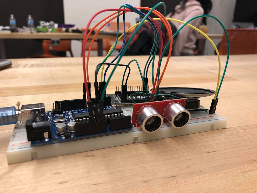
How we built itWe built this device using an Arduino, a NodeMCU, an RGB-LCD screen, a ultrasonic sensor, and a speaker. You will also need the Arduino IDE and Android Studio.
1. Set up the speaker and Arduino. (we decided to use an Arduino Uno). First we hook up your speaker. The speaker has a +ve and -ve lead, so make sure the -ve side is grounded and the +ve side is wired to the output pin defined in the provided code. You can test if your speaker is working by compiling the following code:
> tune(3, 1000, 1000);
where the format is tune (pin#, pitch (200-1500), length in milliseconds);
2. Connect the RGB-LCD screen. Connect Vin to +5V, Gnd to Gnd, SDA to Analog 4 and SCL to Analog 5 (If you are using Arduino UNO). Run the provided code (in attachments) and the LCD screen should say ~ Awake ~ with a white background. Make sure you download the rgb_lcd repository provided by loovee. Also ensure that the contents of the repository and your .ino sketch are in the same directory.
3. Attach your ultrasonic sensor. Vin goes to +5V, Gnd goes to Gnd, Trigger goes to pin 7 as defined in our example sketch and echo goes to pin 8. You can test if the code is working by running the following command alongside the provided code:
> println(getDist());
4. Create a web server using NodeMCU. Using the ESP8266 WiFi library, use the provided code to set up a basic server. You can edit and upload this code onto the NodeMCU using your Arduino IDE.
5. Connect the NodeMCU to the Arduino. Using the designated TX/RX pins, connect the TX of the NodeMCU to the RX of the Arduino and vice versa. You can test this connection by adding the following snippet of code with provided code:
>ArduinoSerial.print(5); //at the beginning of the loop() function of the NodeMCU
If the number 5 appears in the serial monitor of your Arduino UNO, then you did it right!
6. Testing the app with the NodeMCU. You can find the APK file for the app on our GitHub, but feel free to design your own. The app uses the HTTPRequestTask class to send HTTP requests to the NodeMCU. Simply download and install the APK on your Android phone. Power up your alarm (Android/NodeMCU). Connect to the "Hello_IoT" network (password is "12345678"). Open the app. Enter the IP address of the NodeMCU in the given text box (this can be found in your phone's WiFi connection settings). Press the desired time and wait for your alarm to sound!
Finally, wiring the button will take a little trial and error, since each button is made differently, make you want to make sure you are using a pull-down resistor.
And that's it! Enjoy! :)
Challenges we ran intoSome challenges we ran into included issues with HTTP requests, Wifi connectivity, and timing of the alarm.
Specifically, we had issues with connectivity timeouts while sending and receiving signals between the NodeMCU and the app. The HTTP request from the phone is read into the NodeMCU using a timer. However, the default value is too long, so make sure to use the client.setTimeout(100) command to speed up your connection.
Additionally, we had a limited number of pins to work with and one breadboard. Many of the connections required the same pins for input (or we accidentally set to the same pins). As a result, we had to share resources. We needed to find alternatives and prioritize components and their wiring. Reading the documentation for the different components is essential for the rewiring and changing of the pins used for input and output. Overall, this project required working together as a team in order to build one fully functioning device.


Comments