


Hardware components | ||||||
 |
| × | 1 | |||
 |
| × | 1 | |||
Software apps and online services | ||||||
| ||||||
 |
| |||||
Transform your PC setup into an immersive experience with this DIY Real-Time Ambient Lighting System. By syncing your monitor’s colors with a WS2812B LED strip, the lighting extends beyond the display and reacts instantly to on-screen content. This version uses an Arduino Nano with an improved Adalight implementation for better synchronization, data validation, and stability.
This system uses Prismatik as the core PC-side engine. It captures real-time screen colors, maps them to LED zones, and streams RGB data to the Arduino using the Adalight protocol.
The software divides your screen into multiple regions and assigns each region to a specific LED. It continuously sends:
- Header → "Ada"
- LED Count → 2 bytes
- Checksum → validation byte
- RGB Payload → Full LED frame data
Download Prismatik:https://github.com/psieg/Lightpack/releases
Components RequiredAbout the ComponentsArduino NanoThe microcontroller handles serial data from the PC and converts it into LED control signals with precise timing.
- Operating Voltage: 5V
- Input Voltage (VIN): 7V to 12V
- Microcontroller: ATmega328P (8-bit AVR)
- Clock Speed: 16 MHz
- Flash Memory: 32 KB (2 KB used by bootloader)
- SRAM / EEPROM: 2 KB / 1 KB
- Digital I/O Pins: 14 (out of which 6 provide PWM output)
- Analog Input Pins: 8 (10-bit resolution)
Each LED is individually addressable, allowing exact color mapping from different regions of the screen.
- Voltage: 5V DC (Highly sensitive to overvoltage)
- LED Density: 60 LEDs per meter
- Individually Addressable: Integrated driver in each LED
- IP Rating: IP20 (Non-waterproof, for indoor use only)
- Protocol: One-wire digital communication
- Power Note: Significant power consumption at high brightness; requires a stable external supply.
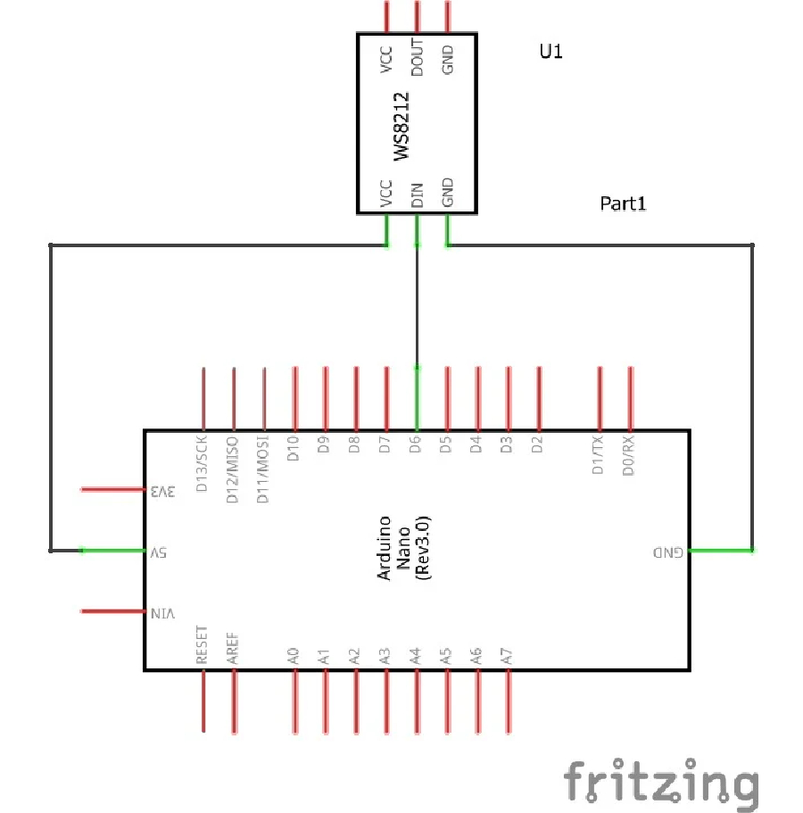
Fig. CIrcuit Diagram
Fig Schemetic Diagram
Wiring Details- LED 5V → External Power Supply (+)
- LED GND → Power Supply (-) & Arduino GND
- LED DIN → Arduino Pin 6
- USB → PC
#include <FastLED.h>- Provides low-level control for addressable LEDs
- Handles timing-critical signal generation internally
#define NUM_LEDS 65
#define DATA_PIN 6
#define serialRate 115200- NUM_LEDS → Total LEDs in strip
- DATA_PIN → Pin used for LED data transmission
- serialRate → Serial communication speed
uint8_t prefix[] = {'A', 'd', 'a'}, hi, lo, chk, i;
CRGB leds[NUM_LEDS];- prefix → Expected header sequence for synchronization
- hi, lo → Incoming LED count bytes (protocol requirement)
- chk → Checksum for packet validation
- I → Shared loop index (used in header parsing)
- leds[] → Buffer storing RGB values for entire strip
FastLED.addLeds(leds, NUM_LEDS);- Initializes LED strip driver
FastLED.showColor(CRGB(255, 0, 0)); delay(500);
FastLED.showColor(CRGB(0, 255, 0)); delay(500);
FastLED.showColor(CRGB(0, 0, 255)); delay(500);
FastLED.showColor(CRGB(0, 0, 0));- Startup diagnostic sequence
- Confirms each color channel works
Serial.begin(serialRate);
Serial.print("Ada\n");- Starts serial communication
- Sends readiness signal to host software
- Header → "Ada"
- LED Count → 2 bytes (hi, lo)
- Checksum → hi XOR lo XOR 0x55
- Payload → RGB data (3 bytes × NUM_LEDS)
for(i = 0; i < sizeof prefix; ++i)- Matches incoming serial bytes with "Ada"
- waitLoop blocks until data is available
If mismatch occurs:
- Resets index
i = 0 - Jumps back using
goto waitLoop - If mismatch occurs:Resets index
i = 0Jumps back usinggoto waitLoop - Ensures exact alignment with packet start
- Reads hi, lo, and chk sequentially
- Each read is blocking using
while(!Serial.available())
if (chk != (hi ^ lo ^ 0x55))- Validates packet integrity
If invalid:
- Resets parsing state
- Jumps to waitLoop
- Entire packet is discarded
- If invalid:Resets parsing stateJumps to waitLoopEntire packet is discarded
memset(leds, 0, NUM_LEDS * sizeof(struct CRGB));- Resets all LED values to zero
- Prevents residual data artifacts
for (uint8_t i = 0; i < NUM_LEDS; i++)- Iterates through all LEDs
Reads three bytes per LED:
- Red
- Green
- Blue
- Reads three bytes per LED:RedGreenBlue
- Blocking reads ensure complete frame reception
- Stores values directly into
leds[]buffer
FastLED.show();- Transfers buffer data to physical LEDs
- All LEDs update simultaneously (frame-based rendering)
- Fully blocking design → waits for complete data before processing
- goto waitLoop used for fast resynchronization
- No partial updates → only valid frames are displayed
- Header + checksum prevent drift and corruption
Host software continuously streams LED color data using the Adalight protocol. The microcontroller enforces strict synchronization using header matching and checksum validation. Only verified frames are accepted, stored, and rendered in a single update cycle, ensuring stable, flicker-free ambient lighting output.
ResultThe system successfully produces real-time ambient lighting that mirrors on-screen content with high accuracy and minimal latency.
- LED colors dynamically match screen edges in real time
- Smooth transitions with no visible flicker
- Stable communication using Adalight protocol (no frame corruption)
- Uniform brightness and consistent color output across the strip
- Low latency response suitable for video, gaming, and general use




Comments