

Hardware components | ||||||
 |
| × | 1 | |||
 |
| × | 1 | |||
 |
| × | 1 | |||
Software apps and online services | ||||||
 |
| |||||
Follow the Snap Circuits platform!
Overview
What Are Snap Circuits?
Snap Circuits® makes learning electronics easy and fun! Learn how to use integrate Snap Circuits® with your hardware. Fun for kids!
Introduction Project
If you have not completed the introduction please go to the Snap Circuits - Introduction project. This project also contains a complete index of Snap Circuit projects.
Let's Get Started
Project Objective
Build an automatic night light that comes on when it get dark.
Building the Circuit
The minimum set requirement for this project is SC-500.
Open the PDF below and follow the directions. The PDF file can also be found in the GitHub repository.
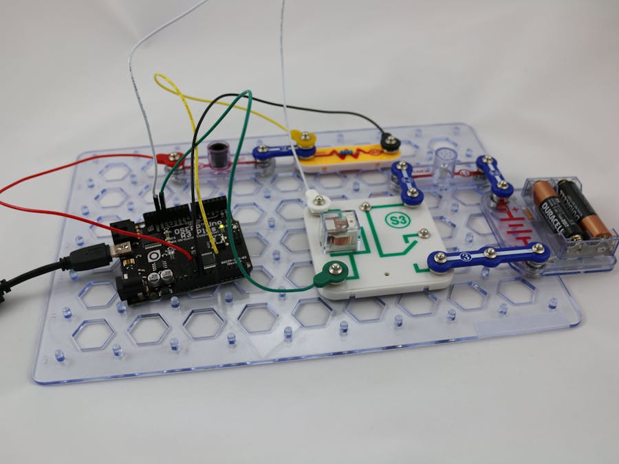
Here are images of the components that you will use to build the circuit.
Loading the Sketch
The attachment below contain the sketch for this project. Click the link below and save this to your computer.
Load this sketch into the Arduino IDE in the same manner as in the Blinking LED project. After it is loaded compile and run it. The sketch for this project will write output to the serial port so you will need to open the Serial Monitor from the Tools menu (you can press Ctrl-Shift M).
How this Works
The Circuit
This project is really two circuits in one. The first circuit monitors the amount of light in the room using the component RP (photoresistor; see the project Measuring Light to see how a photoresistor works). This component is attached to an analog pin on the Arduino. The second circuit uses a relay to turn a light connected to a battery on and off. The relay and battery are required because the Arduino cannot push enough current to light the lamp on its own. The relay is a switch that is activated by current from another isolated circuit. The relay in this circuit is connected to an Arduino digital port that will activate and deactivate the relay. When the relay is activated, the circuit connecting the battery to the lamp is closed and the light turns on. When the relay is deactivated the circuit is open and the lamp turns off.
The Software
The Arduino sketch will monitor the value on the analog pin. When this values falls below a certain value it will set the output of the digital pin to HIGH which activates the relay. When the value on the analog pin is above this threshold it sets the output of the digital pin to LOW which deactivates the relay.
Run the sketch and, using a flashlight, vary the amount of light on the photoresistor. Placing your finger over RP will completely block all light.
Things to Try
- The amount of light needed to trigger the relay is controlled by the value ADC_THRESHOLD which is set to 10. This value requires it to be dark in the room for the light to turn on. How can you make the make the light come on when there is more light in the room?
- There is an optional circuit in the diagram that adds a switch to the light. What does this switch do?
- What happens if the batteries are removed from the battery holder?
- How can you make the light come on when it is light and go off when it is dark? HINT: the value of the photoresistor is read into a variable called adc and compared to the threshold using <= which means "less than or equal to". This line of code determines whether the function TurnLightOn is called or if TurnLightOff is called.


Comments