IntroductionI recently held a hacker weekend event for my team as a way to introduce them to the world of IoT. The attendees consisted of a variety of IT professionals with varying backgrounds with some, little or no experience with electronics.
I knew that using something like an Arduino Uno would provide a great experience, but I wanted to provide an experience that would get everyone past the typical fear of touching electronics. I decided to have everyone build their own Arduino compatible on a breadboard.
I called the board the Mioduino (pronounced me-o-duino). To hear how it sounds put the name into Google Translate and click the speaker icon. Do not let it change it to Miduino (click the link Translate instead Mioduino).
The session was overwhelmingly successful, so I wanted to share that experience here allowing others to hold their own event or just build the board.
Holding the EventThe Mioduino Guide, linked at the bottom of this article, contains all of the necessary information to purchase components, build the board and run the labs. I recommend printing the document for each participant if you plan to hold an event.
The GitHub library also contain a copy of the agenda used. There is also an agenda in the form of a Power Point that can be projected during the event.
The list of components include a Hackerspace Passport. For this event, I had a UX designer create a Hackerspace stamp for our location and we gave everyone a stamped passport and encouraged them to visit other Hackserspaces.
The event ran from 9:30 am to 4:30 pm with a 30 minute reception at the beginning and a 30 minute lunch. Most of the attendees wanted to spend their time building, so they didn't mind the short lunch period.
The event is designed to be instructor led. There are two classroom periods as part of the day. The first classroom experience is meant to cover the basics of building the board and to talk about some of the components of the board. The first classroom session is followed by two labs. The first lab is used to build the board and the second is to test the board with a simple sketch.
There were many questions in the beginning about items covered in the second classroom. The students are naturally more curious as they begin to touch the components and put them together. I found that the approach of building the board and then discussing the concepts worked better because their ability to grasp the new concepts was enhanced by having already used those components.
The second classroom takes a look at several electronic components and delves into some basic electronic concepts. Now that the students have built the board, they are very eager to learn how it works. After the completion of the second classroom, there are eight lab exercises that allow the students to use their new boards.
Obtaining ComponentsAlthough it is possible to hunt down the components from various sources I found it best to order from a single source. I purchased most of the components from Adafruit.
The Mioduino Guide contains all of the information needed to get the components for the board and for the labs. There are a few items that need to be sourced from another vendor. Links are provided in the document for these items. I created two public wishlists at Adafruit to help order the parts. Note that ordering for a single kit can be a little pricy.
This list contains components for 15 kits: https://www.adafruit.com/wishlists/393585
This list contains components for 10 kits: http://www.adafruit.com/wishlists/397786
This list contains components for a single kit: https://www.adafruit.com/wishlists/396935
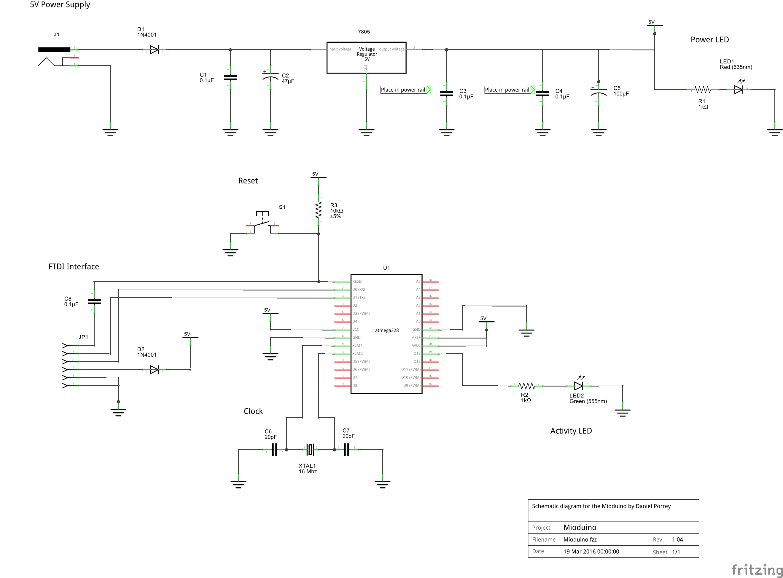
Building the MioduinoThe guide encourages the building of the board in two phases. In the first phase the power supply is constructed. In the second phase, the microcontroller and supporting components are added. After the first phase was completed, a multimeter was used to test the output of the power supply to ensure proper construction. This step helped to build confidence for those who have never built any electronic circuits before.
It is recommended to have at least one pre-built board available for everyone to examine while they build their own board.
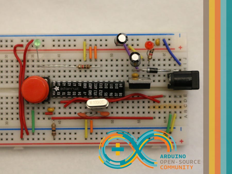
Below are some images of a fully assembled board.
1 / 6 • Top view of the Mioduino.
The Mioduino board will work like any other Arduino board. The board can be configured by adding the hardware to the Arduino IDE. The Mioduino Guide walks through the steps of adding the board to the IDE.
The Mioduino in the Arduino IDE.
The lab exercises and all of the documents referenced in this article can be easily added to the IDE by installing the library. This can be done by opening the library manager and typing Mioduino in the search box.
Mioduino library in the Arduino IDE.
Checkout the 95-page guide to get the full detail of the Mioduino. For complete code, documents, images and everything else necessary, check out the GitHub repositories.


Comments