


Hardware components | ||||||
| × | 1 | ||||
| × | 1 | ||||
Software apps and online services | ||||||
| ||||||
 |
| |||||
_4YUDWziWQ8.png?auto=compress%2Cformat&w=48&h=48&fit=fill&bg=ffffff) |
| |||||
| ||||||
ZigMonitor device is created with the intention of collecting a series of data about the surrounding environment in the room, apartment, office (closed spaces in general), processing this information and sending it further via the Zigbee protocol to a complex Smart Home system created around the NodeRed application.
IntroductionThis project was carried out in partnership with NextPCB; more details here. NextPCB is a printed circuit board (PCB) manufacturer and offers full-service manufacturing and assembly. With over 15 years of experience, the company specializes in the production of multi layer, HDI, flexible and rigid-flex PCBs, complying with international standards such as UL, ISO, IATF, RoHS and REACH
The NextPCB Accelerator is a program designed to support innovators and developers of smart devices. Through this program, NextPCB offers free PCBA prototypes, extensive technical support, and personalized assistance for projects based on emerging technologies such as Beetle ESP32-C6 and RP23502.
The Accelerator aims to facilitate rapid product development and testing by providing access to cutting-edge components and professional manufacturing services. The program is open to both commercial and open-source initiatives, as long as the design is original.
The NextPCB accelerator campaign offers support for many other types of projects, just visit the bottom of the page and choose what suits you.
Good luck!!!
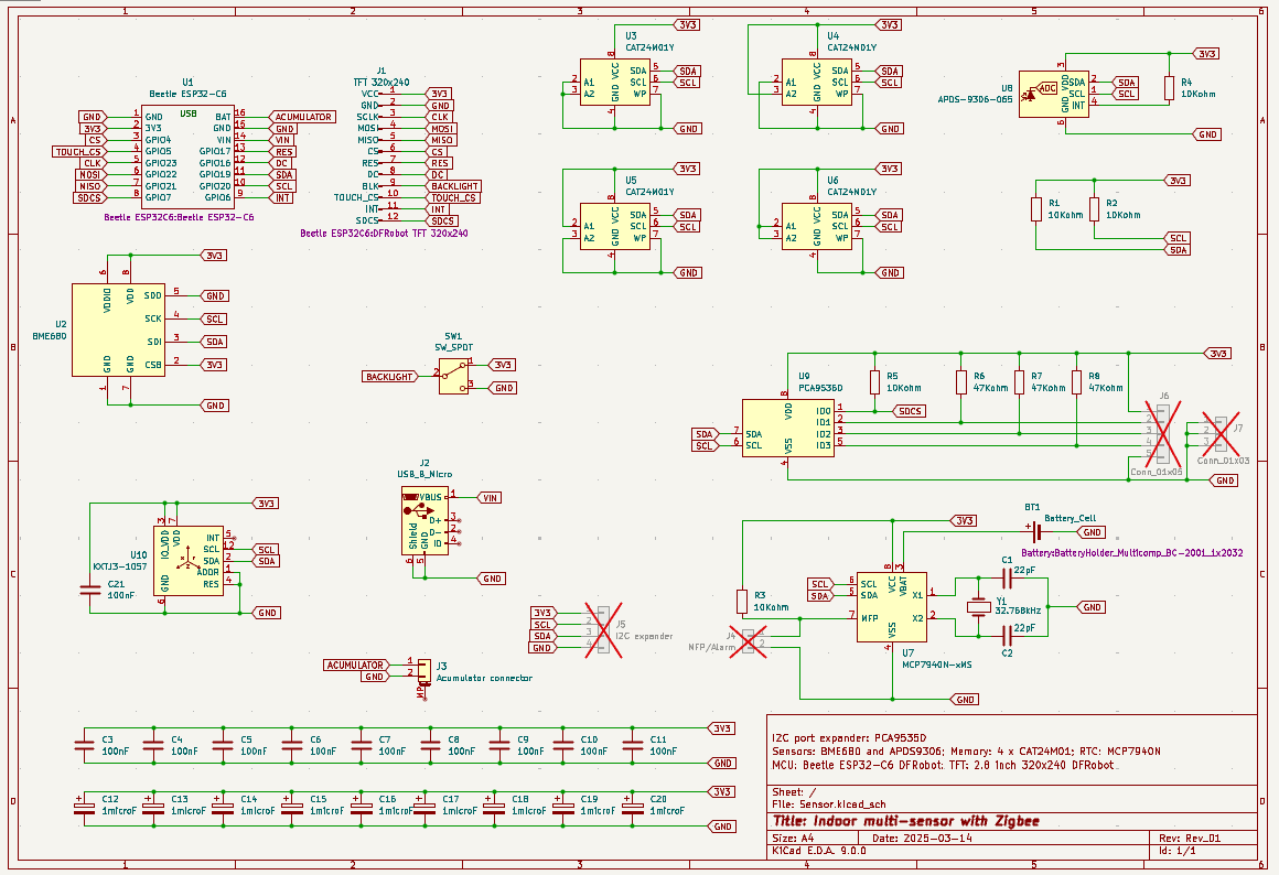
DescriptionThis device, ZigMonitor, is built around the MCU Beetle ESP32-C6 from DFRobot.
I chose this MCU because it offers, in addition to a high-performance 160MHz RISC-V 32-bit processor, various types of communication protocols: Wi-Fi 6, Bluetooth 5, Zigbee 3.0, Thread 1.3 and Matter, making it a good choice for an IoT device.
The MCU, sensors and TFT used in this project are:
- MCU Beetle ESP32-C6;
- BME680 - environmental sensor, used to read temperature, humidity, atmospheric pressure and eCO2;
- APDS90306 - luminosity and proximity sensor;
- KXTJ3 - tri-axis accelerometer.
In addition to these, I also used:
- MCP7940N - RTC;
- PCA9536D - 4 bits I2C port expander;
- CAT24M01Y - 1Mb I2C Serial EEPROM;
- Fermion: 2.8” 320x240 TFT LCD Resistive Touchscreen with MicroSD Card Slot.
The software used to develop the program that will run on Beetle ESP32-C6 is Arduino IDE V2.3.5.
OBS: ESP32-C6 is a "special" MCU because is based on RISC-V arhitecture; because of that, some classic Arduino library are not working native with this MCU; for example, libraries that are used for UI w/o touch screen. This "issue" is present because the SPI definition is different on ESP32-C6 than for "regular" ESP32.
All sensors, RTC and memory are connected to the same I2C bus to MCU. The TFT display is connected to SPI bus (TFT contain three components: touch interface, SD card interface and TFT display itself, all three components sharing the same SPI bus with separare CS pin; see schematic).
Important: during software development, I observed that the serial interface, that is connected to pins 16-Tx and 17-Rx (see here); these pins are used by the esp32 library for debug and is activated after the MCU is powered up and initialized. In this case, even the user try to set other destination for these 2 pins, the serial interface will take control and re-configure these PINs for UART communication and will ignore any user assignment. In this case, to activate the SD interface, I used an I2C port expander, PCA95360 , to control the SC card CS pin (see schematic).
This ZigMonitor sensor will use the new Zigbee implementation for Arduino IDE, based on P-R-O-C-H-Y library. For this project, I combined several examples to send the coresponding data to Nodered over Zigbee network.
WorkingAfter the sensor is powered up, the cod will start up the Zigbee sub-system.
OBS: if the Zigbee subsystem does not start, then the MCU must be replaced or the program must be loaded again from the Arduino IDE. The Zigbee interface is a hardware module that is configured when the MCU is started and is enabled/disabled from the code but also from the settings in the Arduino IDE.
After the Zigbee is started, the UI is initialized and populated with default values for all sensors (direct readings and calculated).
Next, the code will try to connect to one the available Zigbee coordinator. On UI, a counter is started from 10 to 0 (for 10 seconds); during the counting, the Zigbee sub-system will try to connect to coordinator. Now, if the connection is established, on UI will be displayed a message with "connected", colored in green; otherwhise, the message will be "not connect", colored in red.
Next, all sensors are initiated; a waiting time is required for first readings (few seconds) and all computation; once the data is available, it will be displayed in the UI.
OBS: this process is independent of the connection to the Zigbee coordinator.
All the data displayed on UI will be sent also to serial console.
A. UI implementation
UI is created using "Arduino_GFX_Library". It is made in a simple way and displays all the important data of this project. I used this library because it is the only one that allows the customizable use of the SPI pins. To achieve this, I created two separate files, "Arduino_ESP32C6SPI.h" and "Arduino_ESP32C6SPI.cpp" which represent the SPI interface for ESP32-C6. These files are available in download section of the project, in code archive.
For touch-screen I used this library "XPT2046_Touchscreen" which work also with my defined/created SPI files for ESP32-C6.
OBS: during UI development, I tried to use DFRobot_GDL library and LVGL (for this library, the PC EZZ Studio can be used to create a nice UI) but none of them worked because the Beetle ESP32-C6 use other SPI pins and the libraries can not use re-routed, user defined, SPI pins or SoftSPI fucntion. The only library that works fine and accept SPI re-definition PINs is Arduino_GFX.
B. UI design
UI design consist in 7 specific areaS:
1. In the top rectangle is displayed the sensor title;
2. In the second rectangle are displayed readings from sensors without any special computation; temperature, humidity, atmospheric pressure and luminosity;
3. In the third rectangle are displayed calculated values for relative altitube (based on atmospheric pressure), ITU (heat index or index temperature-humidity) and DEW (Dev point); these values can be easily calculated and are consistend based on temp, humi and press values and not depend on the BME680 sensor;
4. In the fourth rectangle are displayed the special values, empiric and estimation; these values are: IAQ (Index of Air Quality), eCO2 (estimate CO2) and TVOC (Total Volatile Organic compounds).
5. In the fifth rectangle is displayed data from KXTJ3 - tri-axis accelerometer; the data are from the sensor directly and are read with 1 second resolution;
6. In the sixth rectangle is displayed the Zigbee status: counter, "connected" and "not connect";
7. In the seventh rectangle is displayed the RTC data, in format HH:MM week_day_dd/mm/YYYY
OBS: data from fourth rectangle, IAQ, eCO2 and TVoC are calculated/estimated without using the Bosh BSEC library for Arduino, because this library is not working on Risc V architecture !
C. RTC working
RTC used in this project is MCP7940N. This chip can retain the date and time if the power is loss with an external 3V CR2032 battery. Also, this chip has 64-byte Battery-Backed SRAM.
In this project, the RTC can be set using one of two methods:
1. using a set date/time function that is present in Setup, in "initialize RTC" section, under "Set date and time, method 1:";
2. using serial connection (through USB connector, from Arduino IDE or oother serial console), in format "YYYY-MM-DD HH:MM:SS"; the week_of_day is automatic calculated and saved in RTC calendar.
D. Zigbee working
To connect to zigbee network and send data to Node Red or other home automation application I used the new implementation of Zigbee for ESP32-C6 from P-R-O-C-H-Y
This new Zigbee implementation use some FreeRTOS tasks, delays (non-blocking) directly in Arduino code.
The sensors data are tyransfered to NodeRed with a 30 seconds period; it is a little bit fast for Zigbee, but, for initial releaseI will keep this way. this period can be modified from FreeRTOS task definition, from Setup area (the description of how to set a task is presented in ZigMonitor .ino file, attached):
zbTempSensor.setReporting(0, 30, 0);          //(1, 0, 1);
zbPressureSensor.setReporting(0, 30, 0);      //(0, 30, 1);
zbCarbonDioxideSensor.setReporting(0, 30, 0); //(0, 30, 0);
zbIlluminanceSensor.setReporting(0, 30, 0); //(1, 0, 1000);E. For APDS90306 (luminosity and proximity sensor) and KXTJ3 (tri-axis accelerometer) I used two external libraries, "AsyncAPDS9306" and "kxtj3-1057", because these are not available directly in library manager from Ardhuino IDE; these libraries are available in download section;
F. Built-in BUT pin. The Beetle ESP32-C6 has a built-in button used for BUT, along with another button, connected to hardware reset. The BUT button is used for Zigbee part, in two ways:
1. short press, aprox 1 second or less --> manually send data over Zigbee to Node Red or other;
2. long press, more than 3 seconds --> reset the zigbee zub-system to re-initialize Zigbee link with coordination.
OBS: the built-in BUT pin is connected to an hardware interrupt that update a PIN status flag variable; I used this way because in Main, a lot of time is "consumed" with sensor readings and parameters calculation and the button status can be easily misted. The button status can be monitored in serial console.
Power consumptionThe ZigMonitor cosume aproximative 150mA at 5V, with Zigbee sub-system activated.
NodeRedData received from ZigMonitor are sent from zigbee2mqtt to NodeRed and then to NodeRed UI.
Note: setup of zigbee2mqtt and Nodered is out of scofe for this project; I already have set this environment in other project.
The files used to configure the specific NodeRed UI are available in download section.
- I noticed that the Beetle ESP32-C6 gets quite hot (almost impossible to hold your finger on) when the Zigbee subsystem is activated; this disrupts the actual reading of the ambient temperature;
- I observed something regarding to new Zigbee implementation for ESP32-C6: simetimes, the Zigbee sub-system is not started after the MCU is powered up oir rebuted; the solution is re-flashing the MCU using Arduino IDE;
- I also noticed that, although ZigMonoitor is connected to zigbee2mqtt and successfully interviewed, the data is not automatically transmitted to it; the solution found is the following: stop ZigMonitor, delete it from zigbee2mqtt and restart the service (or restart the PC containing zigbee2mqtt), start ZigMonitor and connect it to zigbee2mqtt. This solves the problem. As I have noticed, if ZugMonitor is not stopped repeatedly by the user, it works without problems for long periods of time;
- the current implementation of the Zigbee library for ESP32-C6 used in the Arduino IDE does not allow for implicit detection of disconnection from the Zigbee network nor actual monitoring of data transmission to the coordinator; this is not necessarily an issue but I hope it will be updated in the future.
Video demonstrationVideo demonstration of wirking sensor and how manually send data to Node red:
Observe in Arduino IDE serial console specific text used for button monitoring and thet manually send data ober Zigbee.
Next steps1. calibrate the temperature and humidity readings due to the fact that the sensor is near to ESP32-C6 witch become hot after activation of Zigbee sub-system;
2. implement touch screen function (code is already tested using "XPT2046_Touchscreen" and "Arduino_ESP32C6SPI.h" and "Arduino_ESP32C6SPI.cpp" libraries but is not attached);
3. implement an algorithm to save reading data into serial eeprom based on CAT24M01Y memory; then, in other UI screen, create some graphs on days, week and maybe months, with specific data to be displayed;
4. implement a fucntion to display pictures and pictogrames stored on SD card in conjunction with I2C port expander PCA9536 (preliminary code is done for that but is not implemented here!);
5. I will see...the sky is the limit...also, the Beetle ESP32-C6 internal program memory is another limit!
Details of the assembly processA. Pictures from package received from NextPCB, with component and PCBs:
B. ZigMonitor assembled:
At the end of this project, I would like to extend special thanks to NextPCB for their generous support. NextPCB helped me with the PCB design, SMD component placement, and fast delivery, which significantly contributed to the success of the project.
I also thank the DFRobot team, who, in partnership with NextPCB, provided me with essential components such as the Beetle ESP32-C6 MCU microcontroller and the TFT display, without which the project would not have been complete.
I highly recommend NextPCB’s services to anyone developing electronic projects – both for the quality of their work and for the support they provide to the community of creators.
I also encourage you to explore the NextPCB Accelerator program – an initiative dedicated to supporting innovative projects by sponsoring prototypes and providing useful resources for rapid development.
If you have an interesting idea or a prototype in the works, NextPCB Accelerator can be the launch pad you need.
Thank you again to NextPCB and DFRobot for your support!

_t9PF3orMPd.png?auto=compress%2Cformat&w=40&h=40&fit=fillmax&bg=fff&dpr=2)


_Ujn5WoVOOu.png?auto=compress%2Cformat&w=40&h=40&fit=fillmax&bg=fff&dpr=2)


Comments