

Hardware components | ||||||
 |
| × | 1 | |||
| × | 1 | ||||
| × | 1 | ||||
| × | 1 | ||||
 |
| × | 1 | |||
 |
| × | 1 | |||
 |
| × | 1 | |||
| × | 1 | ||||
Software apps and online services | ||||||
 |
| |||||
(Translated with DeepL)
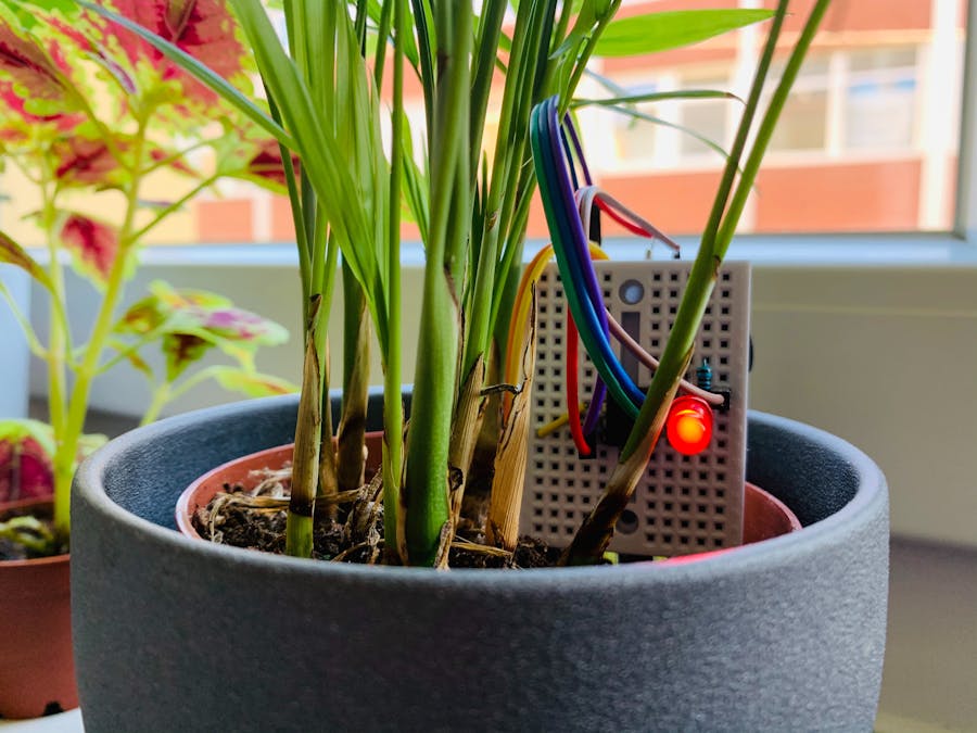
You got a green thumb? Even if you do, this project reminds you to water your plants. Simply place it next to your favorite plant in its pot and calibrate it to the right moisture level. As soon as the soil has become too dry, the LED starts flashing and reminds you to water your plants.
For this project you need:
- ATtiny85
- Humidity sensor
- 3.3V button cell (CR 2032)
- Battery holder with soldered cables
- LED
- 100Ω resistor
- Jumper wires
- Mini breadboard
A good Plant Guard should not stand out too much in a pot next to the plant and should also have an independent power supply. For this purpose the ATtiny85 is a good choice, because you can run it with a 3.3V button cell for a very long time - provided you don't let it measure continuously, but put it into sleep mode most of the time.
With the code of this project you only test every 30 minutes if the soil has become too dry. The rest of the time the plant guard sleeps and draws very little power from the battery. So it should last a long time without problems.
To give the Plant Guard a compact size, use the front and back of the Mini-Breadboard. On the backside you stick some components which you connect with cables on the front side to the ATtiny85. The finished plant guard measures only about 40 x 70 x 40 mm.
Before you start assembling, you have to load the appropriate sketch onto your ATtiny85. You can find the code at the end of this project. Learn here how to upload it to the ATtiny85 with the help of an Arduino Uno.
How to assemble the Plant GuardThe setup of this project takes about 30 minutes.
First the backsideConveniently, there is an adhesive surface on the back of the breadboard where you can attach some components. So first remove the protective foil from the backside. Then stick the battery holder as well as the board and probe of the humidity sensor onto the surface. Press all parts only slightly at first. If everything fits, you can press them harder - they will hold very well on the back.
Let's stay on the back for now. Here you first have to connect the probe to the board. For this you need two cables (best 10cm long), which have sockets at both ends. Attach them as follows:
When you have plugged the sockets to the pins, put the cable around the top of the breadboard. This way they take up the least amount of space.
Now the board of the humidity sensor is next. On it you will find four free pins: VCC (plus), GND (minus), DO (digital output) and AO (analog output). But you only need the first three. So first connect three cables to the pins VCC, GND and DO.
With this you have completed the back of the plant guard for now - time for the front of the breadboard!
Put the ATtiny85 on the boardTake your ATtiny85 and look at it carefully: In one corner of the chip you will find a small round hole. This marks the pin next to it as number one.
Now place the breadboard in front of you so that the probe of the moisture sensor is pointing down. Now carefully place the ATtiny85 in the middle of the breadboard so that the small indentation points to the bottom right. Be careful because the pins of the chip are very sensitive. So be especially careful when you put it on or take it off the breadboard again.
It's best to use a socket for your ATtiny85 to protect it during installation and removal.
This is how it should look like when you are done:
Before you connect the cables of the humidity sensor to the breadboard, first look at the numbers of the pins of the ATtiny85:
As said before, the small indentation marks pin 1 of the ATtiny85. You can get the numbers of the other pins by counting counterclockwise from here.
Now turn your breadboard so that the probe of the humidity sensor points upwards. This way your ATtiny85 points in the same direction as in the picture above.
Now plug the cable from pin DO of the sensor directly next to pin 2 of the ATtiny85. GND goes to pin 4 - this is the negative pole. The pin VCC of the sensor is connected next to pin 7 of the ATtiny85. Here again in the overview:
Attach the LED with resistorBefore you put the resistor on the breadboard, you have to bend it and shorten the legs. This is how the resistor should look after your treatment:
Now take the LED and plug its short leg (cathode) next to the cable at pin 4 of the ATtiny85. Its long leg (anode) has two holes next to it.
Now plug the resistor one row further, so that it connects the anode to pin 3 of the ATtiny85. This should look like this:
Now the most important part: the power supply. Take the two cables of the battery holder in your hand and plug the red cable next to pin 8 of the ATtiny85 and the black one into the last free hole next to pin 4:
The last wireNow you need a little wire bridge. You will need this to calibrate the plant guard so that it sounds the alarm when the soil around it is too dry.
Now plug this jumper between pin 8 and pin 6 of the ATtiny85:
And that was it! Your plant monitor is assembled and ready for calibration.
This is how you calibrate your plant monitorBefore you start, use a screwdriver to turn the potentiometer on the back of the humidity sensor in both directions. When you have connected everything correctly, the LED should turn on and off, depending on how far you turn the potentiometer left and right.
When it is doing so, you can continue:
Place your Plant Guard with the probe next to a plant in the ground. It is best if this soil is just dry enough that you would actually water the plant now. Turn the potentiometer on the backside so that the LED is just about to light up. And that's it - the calibration is finished and the guard knows when to raise the alarm.
Now take out the wire jumper on the breadboard between pin 6 and 8 and put it aside. If everything is correct, the LED should now flash several times every few seconds - the signal that it's time for the watering can.
Then water the plant - the LED will stop flashing until the soil has become too dry and it is time for a sip of water.
The code of the plant guardIn principle, the code consists of the following parts:
- Calibrate the sensor
- Measure the humidity
- Give alarm if the soil is too dry
- Put the ATtiny85 to sleep
At the beginning, however, two libraries must be included and a few pins defined:
The required librariesYou need two libraries for the code, which are already pre-installed:
#include <avr/sleep.h>
#include <avr/wdt.h>
With the library avr/sleep.h you can put your ATtiny85 into sleep mode, which makes sure that its power consumption is reduced considerably. Since the plant guard is battery powered, this sleep mode is especially important.
The library avr/wdt.h is a so called watchdog which you use to wake up your ATtiny85 after a certain time.
Defining the pinsIn total you have to define four pins which your ATtiny85 uses:
#define calibrationPin 1
#define sensorPin 2
#define sensorValuePin 3
#define ledPin 4
Note that the pin numbers do not match the pin numbers you counted through counterclockwise before. If you want to control the pins of your chip in code, you need other numbers, which you can also find in the scheme above.
The numbers for your code start with PB. As you can see, for example, the first pin next to the indentation corresponds to the "code pin" PB5. In the code, however, you leave out the letters and write only 5. 6 pins are left after subtracting the plus (VCC) and minus (GND).
For example, the LED of the Plant Guard is located next to leg no. 3 of the ATtiny85 - in the code you control it with pin 4:
#define ledPin 4In the following explanations from now on always the pin numbers of the code are meant.
In the setup of the sketch, you now define whether they are inputs (INPUT) or outputs (OUTPUT):
void setup() {
pinMode(calibrationPin, INPUT);
pinMode(sensorPin, OUTPUT);
pinMode(sensorValuePin, INPUT);
pinMode(ledPin, OUTPUT);
}Let's get to the loop of the sketch. Here you first check if the jumper for calibrating the sensor is plugged in. The jumper is located between plus (VCC) and pin 1 - that means, your ATtiny85 measures a current (HIGH) at this pin, if the jumper is connected.
If this is the case, only the code for calibration is executed in the loop:
if (digitalRead(calibrationPin) == HIGH) {
digitalWrite(sensorPin, HIGH);
if (digitalRead(sensorValuePin) == 1) {
digitalWrite(ledPin, HIGH);
} else {
digitalWrite(ledPin, LOW);
}
}
First the sensor is switched on by setting the pin for its power supply (sensorPin) to HIGH. In a second query, the LED is switched on when the sensor transmits a measured value of 1 (to the pin sensorValuePin). If the ground is damp, the LED is switched off.
What dry and what wet means you determine yourself by turning the poti on the board of the humidity sensor. As already mentioned, the easiest way to calibrate your plant monitor is to place it in dry soil and turn the potentiometer so that the LED is just lit. If you then water it, it will go out - until the soil is as dry again as it was when you calibrated it.
Measuring the moistureLet's come to the actual measurement of humidity. Here there can only be two states: The soil is too dry or the soil is still moist enough.
First the sensor is switched on for 100 milliseconds:
digitalWrite(sensorPin, HIGH);
delay(100);
If the sensor then measures a 1 and passes it on, it means that the earth is too dry. Then the sensor is switched off again to save power immediately. But for this the LED flashes 10 times up and down.
Finally the Watch Dog is armed so that the ATtiny85 goes to sleep and wakes up after 8 seconds and makes the LED blink again - if you haven't watered the plant in the meantime.
if (digitalRead(sensorValuePin) == 1) {
digitalWrite(sensorPin, LOW);
for (byte i = 0; i < 10; i++) {
digitalWrite(ledPin, HIGH);
delay(200);
digitalWrite(ledPin, LOW);
delay(200);
}
myWatchdogEnable (0b100001);
}
However, if you have done so, the plant guard will of course no longer raise the alarm. It now measures that the soil is moist enough and passes a 0 to the corresponding pin. In this case the LED as well as the sensor goes off and the watchdog puts your ATtiny85 into sleep mode for 30 minutes:
else {
digitalWrite(ledPin, LOW);
digitalWrite(sensorPin, LOW);
for (byte j = 0; j <= 225; j++){
myWatchdogEnable (0b100001);
}
}
The function myWatchdogEnable() is used here, which you can also find in the Sketch. You give this function the byte 0b100001, which sets the timer to 8 seconds. The For-Loop ensures that this 8 second timer is executed 225 times - which gives 30 minutes of sleep.


Comments