/*
*
* DDS Sine Generator mit ATMEGS 168
* Timer2 generates the 31250 KHz Clock Interrupt
*
* KHM 2009 / Martin Nawrath
* Kunsthochschule fuer Medien Koeln
* Academy of Media Arts Cologne
*/
#include "avr/pgmspace.h"
// table of 256 sine values / one sine period / stored in flash memory
PROGMEM prog_uchar sine256[] = {
127,130,133,136,139,143,146,149,152,155,158,161,164,167,170,173,176,178,181,184,187,190,192,195,198,200,203,205,208,210,212,215,217,219,221,223,225,227,229,231,233,234,236,238,239,240,
242,243,244,245,247,248,249,249,250,251,252,252,253,253,253,254,254,254,254,254,254,254,253,253,253,252,252,251,250,249,249,248,247,245,244,243,242,240,239,238,236,234,233,231,229,227,225,223,
221,219,217,215,212,210,208,205,203,200,198,195,192,190,187,184,181,178,176,173,170,167,164,161,158,155,152,149,146,143,139,136,133,130,127,124,121,118,115,111,108,105,102,99,96,93,90,87,84,81,78,
76,73,70,67,64,62,59,56,54,51,49,46,44,42,39,37,35,33,31,29,27,25,23,21,20,18,16,15,14,12,11,10,9,7,6,5,5,4,3,2,2,1,1,1,0,0,0,0,0,0,0,1,1,1,2,2,3,4,5,5,6,7,9,10,11,12,14,15,16,18,20,21,23,25,27,29,31,
33,35,37,39,42,44,46,49,51,54,56,59,62,64,67,70,73,76,78,81,84,87,90,93,96,99,102,105,108,111,115,118,121,124
};
#define cbi(sfr, bit) (_SFR_BYTE(sfr) &= ~_BV(bit))
#define sbi(sfr, bit) (_SFR_BYTE(sfr) |= _BV(bit))
int ledPin = 13; // LED pin 7
int testPin = 7;
int t2Pin = 6;
byte bb;
double dfreqlow;
double dfreqhigh;
// const double refclk=31372.549; // =16MHz / 510
const double refclk=31376.6; // measured
// variables used inside interrupt service declared as voilatile
volatile byte icnt1; // var inside interrupt
volatile byte c4ms; // counter incremented all 4ms
volatile byte icntlow; // var inside interrupt
volatile unsigned long phacculow; // pahse accumulator
volatile unsigned long tword_mlow; // dds tuning word m
volatile byte icnthigh; // var inside interrupt
volatile unsigned long phaccuhigh; // pahse accumulator
volatile unsigned long tword_mhigh; // dds tuning word m
void setup()
{
pinMode(ledPin, OUTPUT); // sets the digital pin as output
Serial.begin(115200); // connect to the serial port
Serial.println("DDS Test");
pinMode(6, OUTPUT); // sets the digital pin as output
pinMode(7, OUTPUT); // sets the digital pin as output
pinMode(11, OUTPUT); // pin11= PWM output / frequency output
Setup_timer2();
// disable interrupts to avoid timing distortion
cbi (TIMSK0,TOIE0); // disable Timer0 !!! delay() is now not available
sbi (TIMSK2,TOIE2); // enable Timer2 Interrupt
dfreqlow=1000.0; // initial output frequency = 1000.o Hz
dfreqhigh=1100.0; // initial output frequency = 1000.o Hz
tword_mlow=pow(2,32)*dfreqlow/refclk; // calulate DDS new tuning word
tword_mhigh=pow(2,32)*dfreqhigh/refclk; // calulate DDS new tuning word
}
void loop()
{
while(1) {
if (c4ms > 250) { // timer / wait fou a full second
c4ms=0;
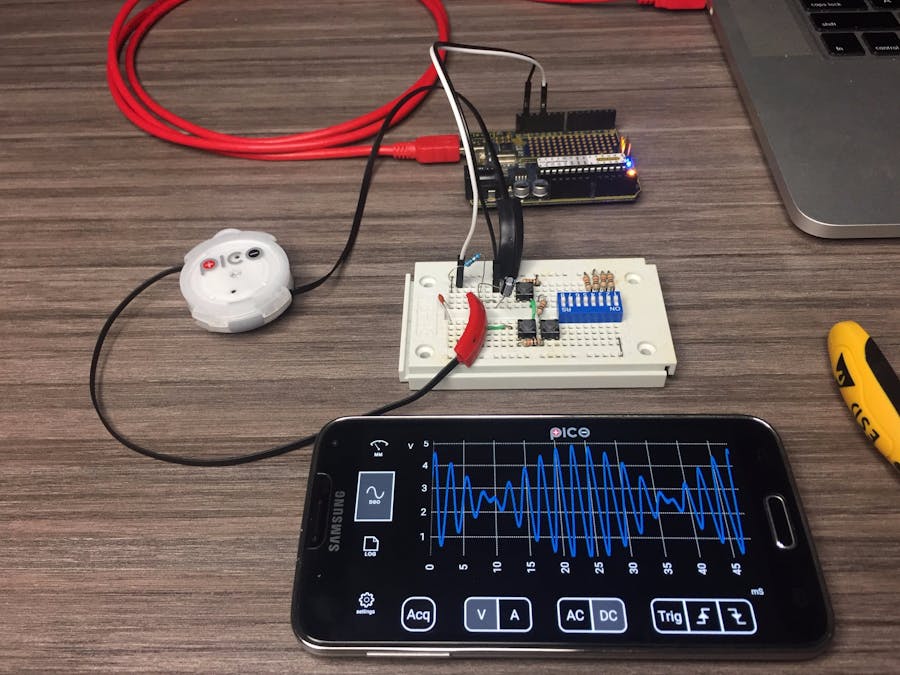
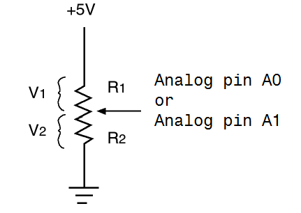
dfreqlow=analogRead(0); // read Poti on analog pin 0 to adjust output frequency from 0..1023 Hz
dfreqhigh=analogRead(1);
cbi (TIMSK2,TOIE2); // disble Timer2 Interrupt
tword_mlow=pow(2,32)*dfreqlow/refclk; // calulate DDS new tuning word
tword_mhigh=pow(2,32)*dfreqhigh/refclk; // calulate DDS new tuning word
sbi (TIMSK2,TOIE2); // enable Timer2 Interrupt
Serial.print(dfreqlow);
Serial.print(" ");
}
sbi(PORTD,6); // Test / set PORTD,7 high to observe timing with a scope
cbi(PORTD,6); // Test /reset PORTD,7 high to observe timing with a scope
}
}
//******************************************************************
// timer2 setup
// set prscaler to 1, PWM mode to phase correct PWM, 16000000/510 = 31372.55 Hz clock
void Setup_timer2() {
// Timer2 Clock Prescaler to : 1
sbi (TCCR2B, CS20);
cbi (TCCR2B, CS21);
cbi (TCCR2B, CS22);
// Timer2 PWM Mode set to Phase Correct PWM
cbi (TCCR2A, COM2A0); // clear Compare Match
sbi (TCCR2A, COM2A1);
sbi (TCCR2A, WGM20); // Mode 1 / Phase Correct PWM
cbi (TCCR2A, WGM21);
cbi (TCCR2B, WGM22);
}
//******************************************************************
// Timer2 Interrupt Service at 31372,550 KHz = 32uSec
// this is the timebase REFCLOCK for the DDS generator
// FOUT = (M (REFCLK)) / (2 exp 32)
// runtime : 8 microseconds ( inclusive push and pop)
ISR(TIMER2_OVF_vect) {
sbi(PORTD,7); // Test / set PORTD,7 high to observe timing with a oscope
phacculow=phacculow+tword_mlow; // soft DDS, phase accu with 32 bits
icntlow=phacculow >> 24; // use upper 8 bits for phase accu as frequency information
// read value fron ROM sine table and send to PWM DAC
phaccuhigh=phaccuhigh+tword_mhigh; // soft DDS, phase accu with 32 bits
icnthigh=phaccuhigh >> 24; // use upper 8 bits for phase accu as frequency information
// read value fron ROM sine table and send to PWM DAC
OCR2A=(pgm_read_byte_near(sine256 + icntlow)+pgm_read_byte_near(sine256 + icnthigh))>>1;
if(icnt1++ == 125) { // increment variable c4ms all 4 milliseconds
c4ms++;
icnt1=0;
}
cbi(PORTD,7); // reset PORTD,7
}

_ztBMuBhMHo.jpg?auto=compress%2Cformat&w=48&h=48&fit=fill&bg=ffffff)


Comments