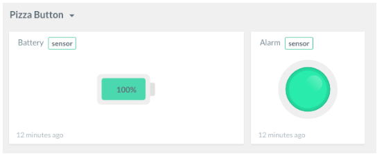
/* This sketch samples the battery level each 24 hrs and triggers on a button push and sends it over using the LoRaWAN protocol
* The sketch has been optimized for minimum battery usages.
*
*/
/* payload structure
* (pos, bitlenght)
* buttonState (0,2)
* bat% (2,2)
*/
#include <RTCZero.h>
#include <Wire.h>
#include <ATT_IOT_LoRaWAN.h>
#include <MicrochipLoRaModem.h>
#include "keys.h"
#include <math.h>
#include "InstrumentationPacket.h"
const int B=4275; // B value of the thermistor
const int R0 = 100000; // R0 = 100k
#define SERIAL_BAUD 57600
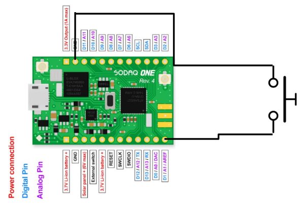
#define enablePin 11
#define pushButton 1
#define ADC_AREF 3.3f
#define BATVOLT_R1 2.0f
#define BATVOLT_R2 2.0f
#define BATVOLT_PIN BAT_VOLT
#define WAKEUP_EVERY_SEC 59 // Seconds part of the clock that wakes up the device
#define WAKEUP_EVERY_MIN 59 // Minutes part of the clock that wakes up the device
#define WAKEUP_EVERY_HR 23 // Hours part of the clock that wakes up the device
RTCZero rtc;
volatile bool rtc_flag = false;
volatile bool pb_Push = false;
volatile bool pb_Reset = false;
MicrochipLoRaModem Modem(&Serial1, &SerialUSB);
ATTDevice Device(&Modem, &SerialUSB, false, 7000); // Min Time between 2 consecutive messages set @ 7 seconds
// Payload data structure
struct payload
{
bool value1;
short value2;
};
payload data;
// Ledcolors
enum LedColor {
NONE = 0,
RED,
GREEN,
BLUE,
YELLOW,
MAGENTA,
CYAN,
WHITE
};
// Interrupt routine
void alarmMatch()
{
rtc_flag = true;
}
uint16_t getBatteryVoltage()
{
uint16_t voltage = (uint16_t)((ADC_AREF / 1.023) * (BATVOLT_R1 + BATVOLT_R2) / BATVOLT_R2 * (float)analogRead(BATVOLT_PIN));
int val = voltage*100/4095;
if (val > 100) val = 100;
return (val);
}
/**
* Turns the led on according to the given color. Makes no assumptions about the status of the pins
* i.e. it sets them every time,
*/
void setLedColor(LedColor color)
{
pinMode(LED_RED, OUTPUT);
pinMode(LED_GREEN, OUTPUT);
pinMode(LED_BLUE, OUTPUT);
digitalWrite(LED_RED, HIGH);
digitalWrite(LED_GREEN, HIGH);
digitalWrite(LED_BLUE, HIGH);
switch (color)
{
case NONE:
break;
case RED:
digitalWrite(LED_RED, LOW);
break;
case GREEN:
digitalWrite(LED_GREEN, LOW);
break;
case BLUE:
digitalWrite(LED_BLUE, LOW);
break;
case YELLOW:
digitalWrite(LED_GREEN, LOW);
digitalWrite(LED_RED, LOW);
break;
case MAGENTA:
digitalWrite(LED_BLUE, LOW);
digitalWrite(LED_RED, LOW);
break;
case CYAN:
digitalWrite(LED_GREEN, LOW);
digitalWrite(LED_BLUE, LOW);
break;
case WHITE:
digitalWrite(LED_GREEN, LOW);
digitalWrite(LED_RED, LOW);
digitalWrite(LED_BLUE, LOW);
break;
default:
break;
}
}
void buttonPushedHandler() {
pb_Push = true;
pb_Reset = false;
}
void buttonResetHandler() {
pb_Reset = true;
pb_Push = false;
}
void setup()
{
pinMode(ENABLE_PIN_IO, OUTPUT);
digitalWrite(ENABLE_PIN_IO, HIGH);
delay(100);
pinMode(enablePin, OUTPUT);
digitalWrite(enablePin, LOW); // If you want to use the pins: 2/3, 6/7 and 8/9 you first have to set pin D11 high.
// Configure the button as an input and enable the internal pull-up resistor (reset)
pinMode(BUTTON, INPUT_PULLUP);
attachInterrupt(BUTTON, buttonResetHandler, LOW);
// Configure PIN d2 as an input and enable the internal pull-up resistor
pinMode(pushButton, INPUT_PULLUP);
attachInterrupt(pushButton, buttonPushedHandler, LOW);
SerialUSB.begin(SERIAL_BAUD); // set baud rate of the default serial debug connection
while((!SerialUSB) && (millis()) < 10000){} //wait until serial bus is available, so we get the correct logging on screen. If no serial, then blocks for 2 seconds before run
setLedColor(BLUE); // BLUE led indicates the device is booting
delay(5000);
setLedColor(NONE);
Serial1.begin(Modem.getDefaultBaudRate()); // init the baud rate of the serial connection so that it's ok for the modem
while((!Serial1) && (millis()) < 30000){} //wait until serial bus is available, so we get the correct logging on screen. If no serial, then blocks for 2 seconds before run
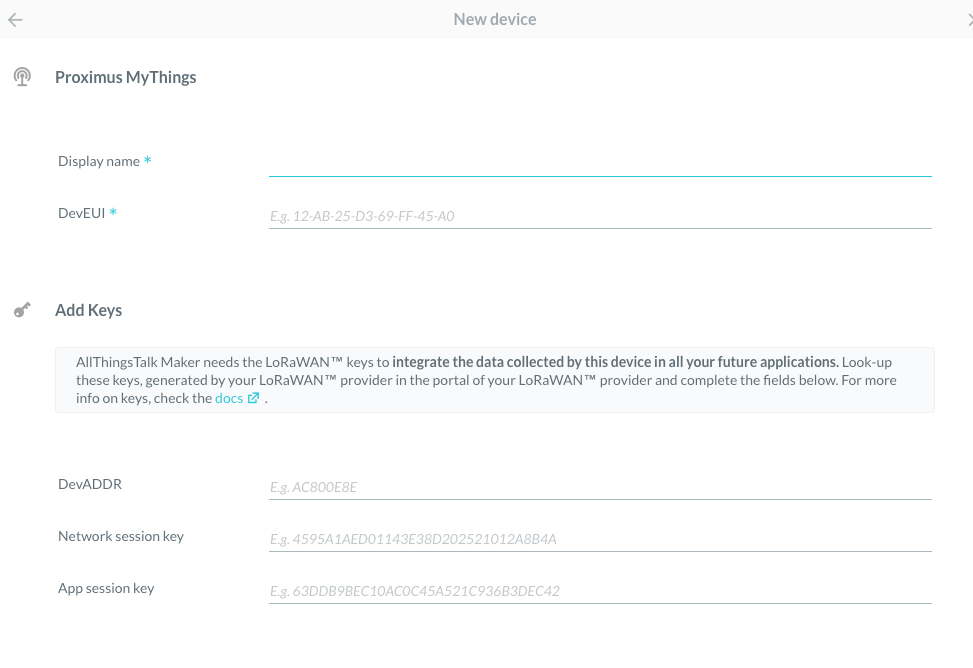
while(!Device.Connect(DEV_ADDR, APPSKEY, NWKSKEY))
Serial.println("retrying..."); // initialize connection with the AllThingsTalk Developer Cloud
SerialUSB.println("Ready to send data");
/* turn of GPS
pinMode(GPS_ENABLE, OUTPUT);
digitalWrite(GPS_ENABLE, LOW);
*/
/*
// disable accelerometer, power-down mode
lsm303.writeReg(LSM303::CTRL1, 0);
// zero CTRL5 (including turn off TEMP sensor)
lsm303.writeReg(LSM303::CTRL5, 0);
// disable magnetometer, power-down mode
lsm303.writeReg(LSM303::CTRL7, 0b00000010);
*/
// turn of USB
// USBDevice.detach();
Modem.Sleep();
rtc.begin();
rtc.setEpoch(0); // This sets it to 2000-01-01
rtc.setAlarmSeconds(WAKEUP_EVERY_SEC); // Schedule the wakeup interrupt
rtc.setAlarmMinutes(WAKEUP_EVERY_MIN);
rtc.setAlarmHours(WAKEUP_EVERY_HR);
rtc.enableAlarm(rtc.MATCH_HHMMSS); // MATCH_HHMMSS
rtc.attachInterrupt(alarmMatch); // Attach handler so that we can set the battery flag when the time has passed.
Sensorsampling();
// payload transmittion
sendData();
// deepsleep
SCB->SCR |= SCB_SCR_SLEEPDEEP_Msk;
__WFI();
delay(100);
}
void Sensorsampling()
{
if (pb_Push) {
data.value1 = true;
}
else {
data.value1 = false;
}
SerialUSB.print("Alarmbutton Pressed: "); SerialUSB.println(pb_Push);
short val = getBatteryVoltage();
SerialUSB.print("Battery Voltage (%): "); SerialUSB.println(val);
data.value2 = val;
}
void sendData()
{
Modem.WakeUp();
setLedColor(BLUE);
SerialUSB.print("#bytes in payload: "); SerialUSB.println(sizeof(data));
Device.Send(&data, sizeof(data), true);
//Device.Send(&data, sizeof(data), false); // without ACK!
Device.ProcessQueue();
while(Device.ProcessQueuePopFailed() > 0) {
SerialUSB.print("QueueCount: "); SerialUSB.println(Device.QueueCount());
delay(10000);
}
setLedColor(NONE);
Modem.Sleep();
delay(500);
}
void loop()
{
if(rtc_flag) {
SerialUSB.print("WAKING UP! ");
rtc.disableAlarm();
Sensorsampling();
// payload transmittion
//sendData();
rtc_flag = false;
rtc.setEpoch(0); // This sets it to 2000-01-01
rtc.enableAlarm(rtc.MATCH_HHMMSS);
}
if (pb_Push) {
setLedColor(RED);
delay(2000);
setLedColor(NONE);
Sensorsampling();
// payload transmittion
sendData();
pb_Push = false;
}
if (pb_Reset) {
setLedColor(MAGENTA);
delay(2000);
setLedColor(NONE);
Sensorsampling();
// payload transmittion
sendData();
pb_Reset = false;
}
rtc.standbyMode(); // Sleep until next alarm match
}


_pEUYSNMbi2.JPG)


_pEUYSNMbi2.JPG)
Comments