


Hardware components | ||||||
_ztBMuBhMHo.jpg?auto=compress%2Cformat&w=48&h=48&fit=fill&bg=ffffff) |
| × | 2 | |||
 |
| × | 1 | |||
| × | 1 | ||||
| × | 1 | ||||
| × | 1 | ||||
| × | 1 | ||||
| × | 1 | ||||
| × | 1 | ||||
| × | 1 | ||||
| × | 1 | ||||
| × | 1 | ||||
| × | 1 | ||||
| × | 1 | ||||
Hand tools and fabrication machines | ||||||
| ||||||
| ||||||
| ||||||
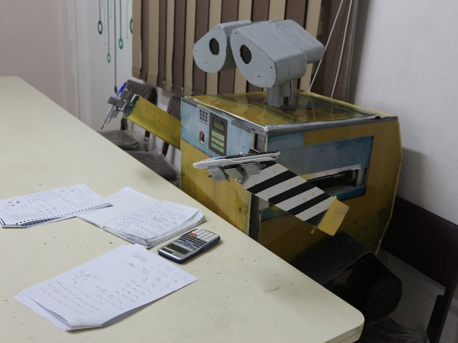
WALL-E is a famous Disney character from WALL-E, the animated film. WALL-E, short for Waste Allocation Load Lifter Earth-class, is the last robot left on Earth. The Pixels team tried to make a real life-sized, fully functional WALL-E with minimum costs.
We are able to wirelessly control WALL-E's leg, hand, arms and head movements. We used voice commands, as well. So we could say that WALL-E is fully functional. This is our first prototype, so enjoy our progress and build yours.
WALL-E is a robot, so it consists of two essential parts:
- Mechanical: The mechanical part includes the structure or the skeleton that allow for movement. Though, it will not be able to move anything without the control part.
- Control: This is the brain or the nervous system which gives the power or the energy to move the body structure.
It is shaped like a cube. We made it from aluminum bars and connected through pins. Note: We used aluminum bars because it is easier to shape than steel; although the steel is harder, inside WALL-E, aluminum bars will be lighter on the motors and this make movement easier. For covering, we used foam board, printed the design of the body, and then stuck the design into the foam board.
Head1) Materials:
There are many materials you can use in making the head. We are going to mention them and the advantages and disadvantages for each.
- Acrylic: Advantages: very hard, not affected by corrosives or climate factors, and light in weight. Disadvantages: very expensive.
- Compressed wood (MDF) Advantages: lower in cost than acrylic, light in weight. Disadvantages: absorbs moisture from the air and liquid, therefore that will affect it in two ways. First, it will develop a very dank smell. Second, it will expand and breakdown after a while, so this material is not practical for the head.
- Compressed foam board Advantages: very cheap compared to acrylic and MDF, very light, you can easily shape it. Disadvantages: It can be eroded by any spray.
2) Design:
If we designed the head as a solid part, it would be very heavy and this will increase the torque of the head. Therefore, we need a motor with high torque. And to make the head a solid part, we had two options: first by a molten cast model (this would be very expensive and time-consuming), and second by 3D printing (which also would be very expensive).
To resolve this problem, we made the head from compressed foam board lamination and glued the lamination together to make them one part. This method was very exhausting as you need to glue the lamination by hand. But it is very cheap in comparison with the two other methods and it will be lighter than the other two.
We designed the head on SOLIDWORKS and then cut the compressed foam board via laser cutter machine so it would be easy and fast. The head consisted of two front parts and two back parts. We connected them by making small holes in every part and connected them through with a wooden rod.
We used two servo motors to move the head: one for left and right, and the other for up and down.
3) The final view:
As previously mentioned about the compressed foam board disadvantages, it can be eroded by any spray. Therefore, we had to cover it with paper maché to protect the foam board from eroding and then painted it with gray spray paint.
Neck1) Material:
Acrylic: we used it because we needed material that can handle the head weight and will not breakdown.
2) Design:
We designed the neck on SOLIDWORK and then cut the acrylic with a laser cutter. The design is that of a cylindrical-like part similar to the human neck. We assemble the neck parts and assemble the neck with the head by using a hot glue gun.
Movement mechanism (Legs)Consists of (materials & components):
- Motors
- Free wheels (pulleys)
- Rubber belt
- Rubber covers
- Aluminium body
Steps for assembling the leg parts:
1. Make the structure of the legs with aluminum bars. Connect three bars: two horizontal and parallel, and the third bar is vertical between them. It should make a shape like a capital letter i.
- The horizontal axis: You have to allow one side of the bar to open to fix motors and make holes in the other side to fix the free wheels (pulleys).
- The vertical axis: It is the connecting bar between the inclined and the horizontal bar.
- The inclined axis: You need to make four holes to fix the free wheels.
2. We used a right angle hollow shaft motor to rotate the wheels in all directions (forward, reverse, right and left).
3. The wheels are made of artelon material. There are two different sizes. The larger ones are driven by the motors and the smaller ones rotate freely.
4. Put the rubber cover around the wheels to increase the friction between the wheels and the belt. This will also increase the friction between the belt and the ground.
5. Put the belt around the wheels.
6. Connect two legs together by connecting aluminum bars between them. These bars act as a suspension system for the body of WALL-E. And finally, paint the legs with black spray paint.
We made the structure of the arms by connecting two aluminum bars. In this part of WALL-E, there are two kinds of motions: linear and circular.
- Linear motion: In this motion, we can move forward and backward. You can make this movement by using a drive screw with DC motor.
- Circular motion: We used it to move WALL-E's arm in a rounded motion similar to our arms.
There are many kinds of motors such as Servo, Stepper, and DC.
- Firstly, we used servo motors with high torque, but it made it such that the gear box could not stand. There was high stress if anyone wanted to move the arms when the power is off.
- Therefore, we thought to use stepper motors, but it was very large with the required torque.
- Finally, we decided to use DC motors and see if it works or not!!
DC motors worked very well as the speed was reduced because the torque was very high.
We faced some problems:
- Vibration from drive screw. We overcame it by putting a bearing in the end of the screw to hold it and reduce vibrations.
- Connection between nut power screw and the arm. We overcame this by adding a cylindrical part and weld in it the nut of the power screw on one side, and in the other side, we put the motor inside it to allow the motor rotation.
Here we go.
- batteries
- Arduino
- 1 Shield
- wires
- motors
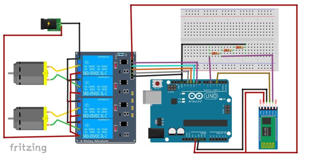
Of course, we need motor drivers or relays to control the motors' directions. We used relay modules as the motor drivers cannot stand the current of our motors.
In WALL-E, we used DC motors as we mentioned in the mechanical part. For controlling Arduino, there were too many options like using a Bluetooth or WiFi module, or USB or wireless gamepad.
- As mentioned, we used 1Shield. It connects with a phone by Bluetooth and it has many functions or shields inside it. You can see all its’ features from the 1shield site. We are going to use Gamepad Shield. It is like a joy stick or Bluetooth module Android app and you can see more about it from GamePad Shield. As well, we used Voice Recognition Shield from 1 Shield; you can also read more about it from Voice Recognition Shield.
Wall-E's hands are much like human hands and its movement will be up and down. We could have used servo motors for this but there was a problem. The torque on the axes of the motors was very big. Therefore, there were three options:
- Use a servo motor with the proper torque but it will be expensive.
- Use a stepper motor but it will be expensive too.
- Use a DC motor.
We tried the DC motor and it was so perfect; it can stand the torque. Its rpm was fine, not too fast, and its cost is acceptable.
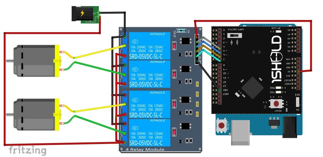
And so, we used relays to control the motors as we mentioned in the movements. But we used a Bluetooth module to control the arms.
After connecting the circuit, you just need to download the app on your smart phone and start controlling the arms.
We did not use the 1Shield to control the arms as there were not enough buttons on the gamepad. Therefore, we had to make the hand controls separate from the movement.
VoiceThere are many techniques you can use to talk to WALL-E and making WALL-E reply to you.
You can put a microphone inside the body to talk with Wall-E, but does not work well because the surrounding environment must be very quiet for receiving the voices and you should be but so close to it. That was not working so, we tried to find another way to solve this issue. We decided to use the phone microphone and connect it with the Bluetooth module to the Arduino.
There was a voice recognizer shield and a voice shield. The first one is used to understand the voices and the other is used for replying. But that was not effective for many reasons; the most important reasons were that the voice shield had limited voices to save in it and we will need to connect two shields with the Arduino, which would be a waste of power.
Therefore, we search for a shield compile between them.
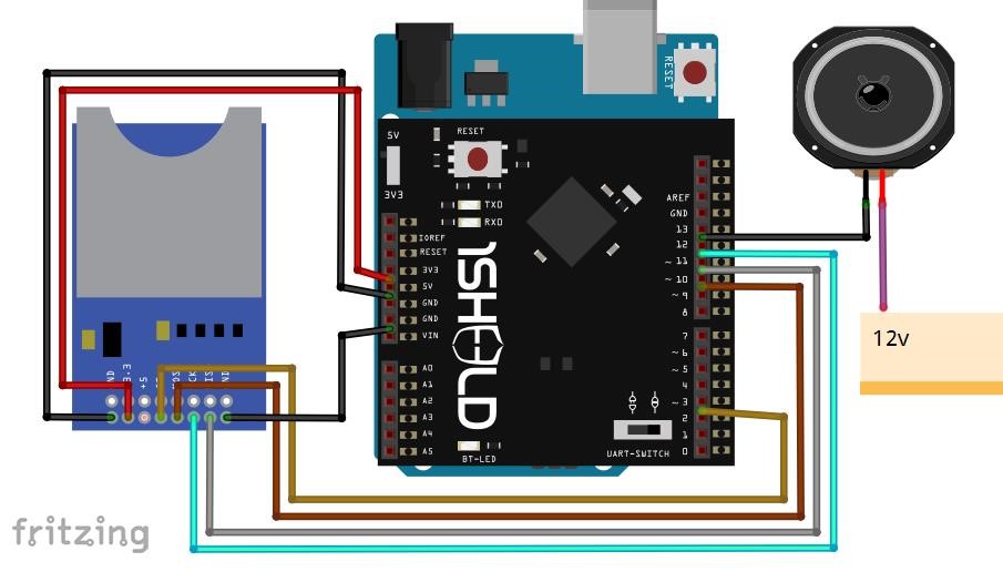
There was a shield that enabled us to use all sensors in the phone including a voice recognizer. Its called 1Shield and we mentioned it in movement section so you can back to it. That was an easier way. To make WALL-E reply to you, you will need an SD card module to play the sounds you want. The advantages are you can play any number of sounds you like and you can make your own voices. If you connect the SD module directly to the speaker, its voice will be very low so we searched for a solution.
We tried many circuits. Here we mention them:
- The first circuit uses a transistor and bunch of capacitors and resistors. It did not amplify the output very much so we had to search for another solution.
- The second circuit uses an op amp LM386, but there was noise in the output voice too.
So we decided to use a stereo speaker.
There are some issues in the voice signal itself. You must change its frequency and the amplitude to a proper number in order to remove the noise and to make the volume is higher. You can use this site to change the frequency and the amplitude (http://audio.onlineconvert.com/convert-to-wav).
If you are going to buy speakers, the smaller your ohms, the clearer the output voice will be.
Simply clip the Pulse Sensor to your earlobe or finger tip and plug it into your 3 or 5 Volt Arduino, and you are ready to read heart rate! The 24" cable on the Pulse Sensor ends with standard male headers so there is no soldering needed.
Our goal is to find successive moments of instantaneous heart beat and measure the time between. The main theory is that when the heart pumps blood through the body, with every beat there is a pulse wave (kind of like a shock wave) that travels along all arteries to the very extremities of capillary tissue where the Pulse Sensor is attached.
Pulse Sensor Amped responds to relative changes in light intensity. If the amount of light incident on the sensor remains constant, the signal value will remain at (or close to) 512 (midpoint of ADC range). More light and the signal goes up. Less light, the opposite. Light from the green LED that is reflected to the sensor changes during each pulse.
For this you need a LCD to show the sensor readings. All you need to do is attach the Arduino to the LCD and make them appear on LCD screen.
FinishingWe took the dimensions of WALL-E's body and printed the design of WALL-E on paper. Then we put on foam and fixed it to WALL-E’s body by using double-sided tape.
- The front is one part.
- The back are three parts.
- The two sides each side two parts.
- The other parts: the arms and the legs.
We used spray paints with Black, Yellow and Silver colors.

bluetooth and motors


Comments