


Hardware components | ||||||
| × | 1 | ||||
| × | 1 | ||||
| × | 1 | ||||
| × | 1 | ||||
| × | 1 | ||||
| × | 1 | ||||
| × | 1 | ||||
| × | 1 | ||||
| × | 1 | ||||
| × | 1 | ||||
| × | 1 | ||||
| × | 1 | ||||
| × | 1 | ||||
| × | 2 | ||||
| × | 1 | ||||
 |
| × | 2 | |||
| × | 1 | ||||
Software apps and online services | ||||||
| ||||||
| ||||||
| ||||||
Hand tools and fabrication machines | ||||||
 |
| |||||
 |
| |||||
In 2023, I interned at a power plant serviced by an Independent Power Producer (IPP), and there was a mundane task I had to do every Tuesday— I had to go to about 25 different locations to get the energy consumption readings from electricity meters and log them in an Excel sheet.
Now, in 2026, after some research, I understand the problem better. IoT meters are expensive, and it would be an extreme cost overhaul to change thousands of meters dispersed at different locations. Then the solution hit me— why not build a retrofit solution that wouldn't require full meter replacement by taking advantage of the RS-485 port on electricity meters?
Definition of TermsBefore I get into the interesting details. I will define some important concepts used in this project:Modbus
Modbus is essentially the "old reliable" of the electronics world, acting as a universal language that allows different devices to talk to each other. It employs a master-slave architecture where one master controls multiple slaves.
Each slave has a unique number called a 'Slave ID' which the master uses to issue commands to the slave.
Modbus itself is an application-layer messaging protocol that organizes data into 16-bit registers. These 16-bit registers are read using commands that are sent to the slave, which forces the slave to return the requested data.
RS-485
Modbus is the protocol, and RS-485 is the physical medium used for Modbus communication. Typically, microcontrollers don't have an RS-485 built into them, so we would use a transceiver chip that converts UART to RS-485. This will enable us to send RS-485 type signals over our MCU's UART lines,
PPPOS
Typically, when using cellular modems, we send AT commands to the modem to make it do things; however, with PPPOS, the ESP32 uses the cellular modem the same way your phone or laptop uses its cellular modem. No need for AT commands, just make your regular web request as if you were using Wi-Fi on the ESP32, and the pppos client will route the data to the internet using the cellular modem. I myself just discovered it while building this project.
How it worksThe basic operation of the device is as follows:
- The ESP32 establishes communication with our cellular Modem A7670G and creates a PPPOS client. This gives the ESP32 internet access.
- A config file is uploaded to the ESP32— the file contains the serial configuration for the slave device and the 16-bit register addresses for that specific slave. In our case, the slaves are meters.
- The ESP32 reads the config file and uses the serial configuration and data addresses there to establish communication with the meter and get the meter readings.
- The ESP32 then uses MQTT to send the data to our dashboard on Thingsboard, where we can visualize the data.
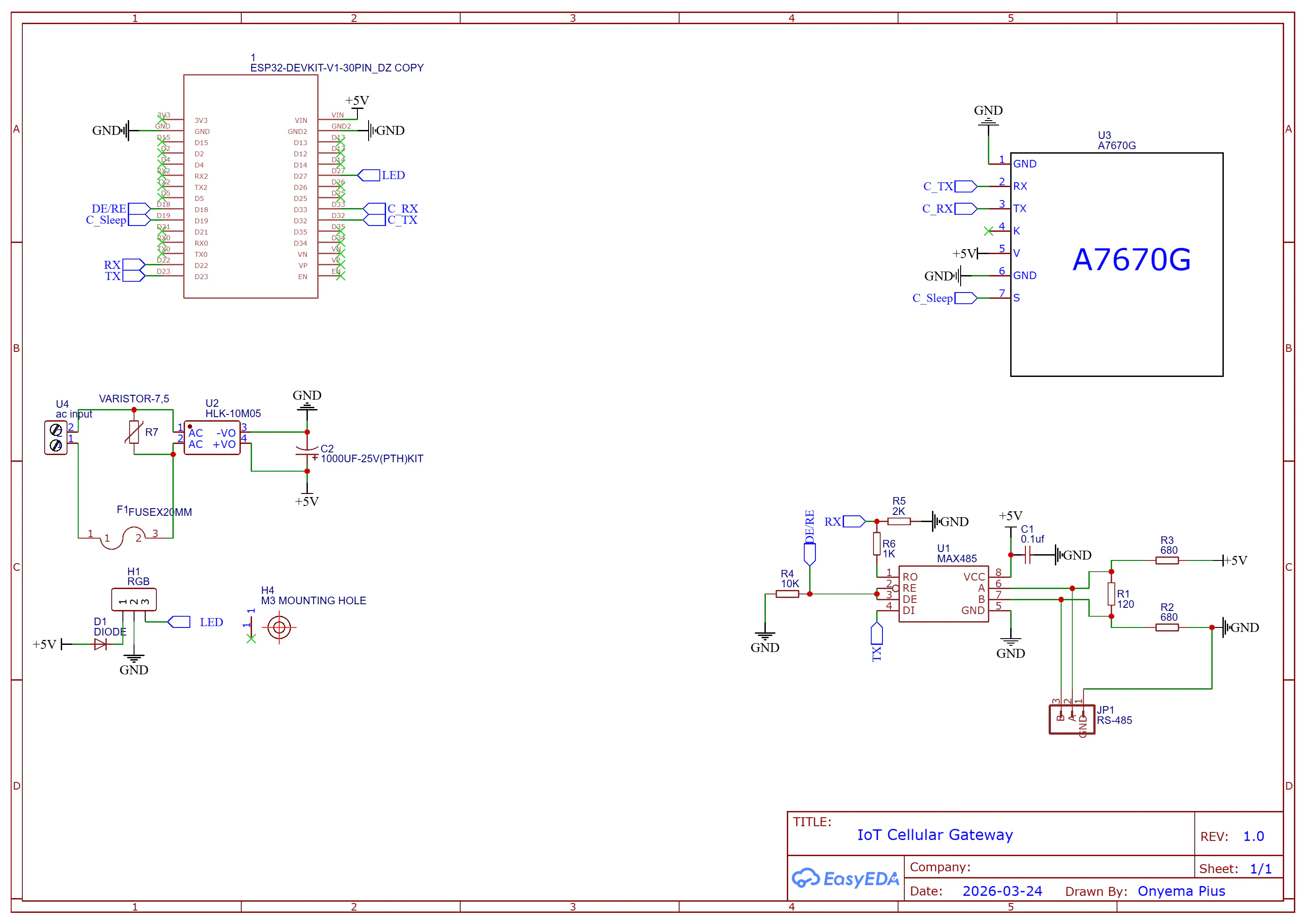
Below is the Schematic diagram of the board
ThingsBoard is an open-source IoT Platform for device management, data collection, processing, and visualization for IoT solutions.
To create your own dashboard, head over to Thingsboard and create an account. Then, follow the steps below to set up our things board dashboard:
Step 1: Create a device
In the left navigation pane, under Entities, click Devices and add a new device. Give the device a name and label, and leave the other options as is.
A new screen should pop up about connectivity. Click on MQTT and copy the MQTT command. We will need the parameters in the command for our code later.
Below is a table to help explain what each parameter in the command represents.
Using the table as a reference, note your parameters. You will need it later in the code.
Step 2: Create a dashboard
I have already created the dashboard, so there is no reason for you to recreate it. You can just import the dashboard. The dashboard schema can be found in the GitHub repository.
In the left navigation pane on the screen, click on Dashboards, then Adddashboard, and then Import dashboard.
Give the dashboard a name and an optional description, then click Add.
Step 3: Dashboard Configuration
For a better user experience, I made the dashboard have two states. One state allows us to see all the devices in one single view on a table. I call this state the FleetOverviewstate.
The other state allows us to have a more in-depth look into the device data. I call this state SingleDeviceState.
Before we get into the code. It would be important for us to understand Modbus registers and how they work. This will be important when you want to create your own configuration files for your own meter.
Above is a Modbus register table. Using the table, to read the voltage on phase 1, what we need to do is read the address(direction) 1848. The same applies to any register you want to read. The above image is the Modbus registers for my specific meter; you have to find the Modbus register of your specific meter. This kind of information can easily be gotten from the manufacturer's website, or you could email the meter manufacturer.
The Config File
The config file is where the serial configuration of your meter and the Modbus addresses you want the ESP32 to read are stored.
{
"meter_info": {
"meter_name": "Circutor CIRWATT B",
"phase": 3,
"slave_id": 1
},
"serial": {
"baud_rate": 9600,
"data_bits": 8,
"parity": "None",
"stop_bits": 1
},
"settings": {
"endianness": "big",
"addr_offset": 0
},
"regs": {
"V1": {
"addr": 1842,
"func": 3,
"qty": 2,
"divider": 10,
"unit": "V"
},
"V2": {
"addr": 1844,
"func": 3,
"qty": 2,
"divider": 10,
"unit": "V"
},
"V3": {
"addr": 1846,
"func": 3,
"qty": 2,
"divider": 10,
"unit": "V"
},
"I1": {
"addr": 1848,
"func": 3,
"qty": 2,
"divider": 100,
"unit": "A"
},
"I2": {
"addr": 1850,
"func": 3,
"qty": 2,
"divider": 100,
"unit": "A"
},
"I3": {
"addr": 1852,
"func": 3,
"qty": 2,
"divider": 100,
"unit": "A"
},
"power": {
"addr": 1868,
"func": 3,
"qty": 2,
"divider": 100,
"unit": "kW"
},
"pf1": {
"addr": 1854,
"func": 3,
"qty": 2,
"divider": 100
},
"pf2": {
"addr": 1856,
"func": 3,
"qty": 2,
"divider": 100
},
"pf3": {
"addr": 1858,
"func": 3,
"qty": 2,
"divider": 100
},
"freq": {
"addr": 1860,
"func": 3,
"qty": 2,
"divider": 10,
"unit": "Hz"
},
"energy": {
"addr": 1800,
"func": 3,
"qty": 2,
"divider": 1,
"unit": "kWh"
}
}
}
You are to make one of these with the same structures as the one above, but update them with your meter parameters. Let's go over some of the keys in the configuration file.
meter info
The phase and the slave ID are the most important here. Most devices have their slave devices set to 1 by default unless they have been changed by someone. The best option is to check the meter manual or contact the meter manufacturer. The phase is basically how many phases your meter has.
serial
You can get the serial information from your meter manual. You have to fill in the right serial configurations; otherwise, the ESP32 won't be able to achieve communication with your meter.
Registers
The registers are the memory that the ESP32 will read data from. If the meter were single-phase, we would have had only "V1" and "I1". The "addr" key is the address of the parameter we want to read, the "func" key is the command we are sending to the Modbus slave (meter); 3 stands for ReadHoldingRegister. The "qty" key represents the number of memory addresses we are reading. Remember, Modbus uses 16-bit registers, so if a parameter uses 32 bits, it uses two memory addresses.
Divider
Modbus can't store floats, so it stores the values in its registers without their decimal. So the divider is a value that the actual value from the register must be divided by to get the real value.
The CodeI built this project using ESP-IDF. To use ESP-IDF, you can just download the ESP-IDF extension on VS Code and then follow the prompts you get to install all the required files.
Once everything is installed correctly, close VS Code and then download the code from the GitHub repository, and then open the folder using VS Code as seen in the image below:
Configuration
Before the code is ready to be built and flashed, you need to update some custom parameters, such as APN and the various MQTT parameters from Thingsboard, which I asked you to copy and keep.
Once VS Code has loaded, click on the ESPRESSIF icon on the left bar and select SDKConfigurationEditor (menuconfig). Follow the image below to set the parameters
All the MQTT parameters are unique to your specific device; the only constant thing is the MQTT URL, you can just copy mine as is in the image above.
The APN is very important; without it, the MODEM cannot access the internet. You can find the APN of your cellular network by checking their website or just googling it.
Don't forget to save. Before you click on Build,Flash, and Monitor to upload, select the upload method and COM port at the bottom taskbar of VS Code
You can also change the ESP32 board being used if you are using another ESP32 variant like the C, S, or H series. Click on the ESP32 just beside the COM port and select your variant.
If you do this, you would have to go back to the menu config and update the pins used since the pin map is different for each variant.
Now you can click Build,Flash, and Monitor to upload the code to the ESP32.
Connecting to a MeterYou can power the board via USB or the board's AC input.
To connect the board to the meter, connect the board's GND, A, and B from the 485 terminal of the board to their respective pins on the meter (meter GND, A, and B).
Using jumper wires creates a very loose connection. If your meter has screw terminals for its RS-485 line, use that, or if it uses RJ45, use that. Mine uses DB9. The main thing here is that A goes to A, B goes to B, and GND to GND. As far as you've got this, the port you're using for connection doesn't matter much.
To enable the ESP32 to be able to communicate with your meter, you need to upload the meter configuration file to the ESP32. I have already explained how the file works in previous sections, so let's get right to it.
Once the code is uploaded and running, open your WI-FI settings on your PC and connect to MG001
Once connected, open your browser and type in this address in the URL bar
192.168.4.1, and you will be greeted with a Web portal where you can upload the meter configuration file
after you have attached the file, click upload to ESP. When ESP32 has successfully received and saved the file, it resets and uses the parameters in the configuration file to start getting data from the meter.
I have abstracted most of the code complexity in the header and cpp files, so as to make the main.cpp simple and easy to understand. However, if you want to get into the nitty-gritty of the code base, I have added sufficient comments to all code files in the code base to aid your understanding. Now, into the main. cpp file:
1.Headers and Includes
The file imports standard C/C++ libraries, FreeRTOS libraries for task scheduling and delays, and ESP-IDF drivers for UART, GPIO, and logging.
Crucially, it includes several custom project headers:
- ArduinoJson.h: Used for parsing the configuration file and formatting the outgoing MQTT payload.
- config_server.hpp: Manages a local server (likely a web server over Wi-Fi AP) where a user can upload or set the meter's configuration.
- modbus_handler.hpp & modbus_parser.hpp: Handles the RS485 Modbus RTU protocol to talk to the physical energy meter.
- myPPP.h: Manages cellular modem communication using the Point-to-Point Protocol (PPP) to get internet access.
- my_mqtt.h: Manages the MQTT connection to send data to the cloud.
2. Variables and Tags
It defines string tags used by ESP-IDF's logging system (ESP_LOGI, ESP_LOGW) to prefix console output, making debugging easier. It also defines a global boolean config_file_exists to track whether the device has been configured yet.
3. Initialization (app_main)
app_main is the main FreeRTOS task. It immediately starts the configuration server so users can configure the device if needed. It then checks if a configuration file already exists
It allocates two JSON documents in memory: one to hold the static configuration settings and another to temporarily hold the live readings before they are sent over MQTT.
This section initializes the device's internet connection. It configures a cellular modem, establishes a PPP data connection, and then configures the MQTT client to prepare for data publishing.
4. Modbus Configuration
If a configuration file is found, it loads it from the filesystem, parses it into the meter_config JSON document, and uses those settings (such as baud rate, parity, etc.) to initialize the RS485 UART interface for Modbus communication.
5. Main Polling Loop
The firmware enters an infinite while(1) loop. If the device is properly configured, it begins polling the meter.
It checks the configuration file to see how many phases the energy meter has (e.g., 1 for single-phase, 3 for three-phase). It loops through each phase, dynamically creates JSON keys (e.g., "V1", "I1", "V2"), uses get_modbus_parameter() to fetch the corresponding reading from the Modbus meter, and stores it in the `meter_data` JSON object.
After getting phase-specific data, it grabs general parameters like frequency, total energy, and total power, adding them to the JSON payload.
6. Publishing and Delay
It serializes the complete meter_data JSON object into a string and publishes it to an MQTT broker with a QoS (Quality of Service) of 1. It prints the payload to the console and then puts the task to sleep for exactly 2 seconds before repeating the loop.
If no configuration file exists, the code skips all Modbus and MQTT logic and simply sleeps for 1 second. This prevents the FreeRTOS watchdog timer from thinking the system has frozen and rebooting the ESP32 while waiting for the user to upload a configuration.
DEMO VIDEODebuggingMQTT not connecting
- Do you have an active mobile data plan on the SIM card?
- Are your MQTT parameters correct?
MODBUS RTU is returning negative values
The negative values are actually error codes. This is what they mean:
- -1 = no response from slave
- -2 = CRC error
- -3 =incompatible config file
If you are getting -1, it is likely an issue with the connection to your slave(meter). The meter could be off or not responding, or your wiring is wrong.
If you are getting -2, it likely means everything is working fine, but there is an error in the response from the meter. This is likely from electromagnetic interference.
If you are getting -3, there is something wrong with the values you put in your configuration file. You might have put the wrong address.
ExtrasThe cool thing about this board is that it can work as an IoT node for any RS-485 device, so you can always update the firmware to make it work with other RS-485 sensors and meters


Comments