1 / 3 • This is a diagram depicts the finished LED light set up, with most of the connector wires omitted, and with an optional breadboard (green rectangle) that was added for organizational purposes.
I built this light for a research project that required me to test the effect of different frequencies of flashing light on the growth of algae. It turns out that algae is more photosynthetically efficient at certain light frequencies (this paper outlines an example of the phenomenon and its importance, if you're interested!). You could test this light out on your own house plants, or use it in your own science experiment. If there are any other uses, I'd love to know! Also, I had pretty much zero experience with electronics before starting this project, so if anyone has any suggestions for improving the project, or any mistakes I may have made, please let me know! The light is up and running now, so I can verify that it works! I'll upload a video soon.
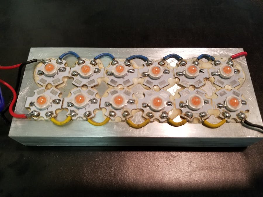
The complete LED light configuration consists of two strands of high-powered LEDs, wired in parallel and mounted on an aluminum heat sink. Power is supplied to the light through a 36 V constant-voltage controller. The frequency of the flashing is directed by an Arduino Uno microcontroller, through a solid-state relay (SSR). A temperature data logger is included in the apparatus—it reads the temperature within the growing area and logs it to an SD card via the Arduino. It can flash at over 100 hertz.
Begin by measuring the approximate resistance of each LED bulb. This can be done by wiring each bulb to a 6-volt power source and measuring the ohms of the bulb with a standard multimeter. Wait approximately 15 minutes until the LED’s temperature stabilizes, record the resistance, and label the LEDs. Then, organize the 12 LED bulbs into 2 groups of 6. The cumulative resistance of the LEDs in each group should be roughly equivalent, which will help prevent thermal runaway.
After the LED groups are sorted, begin the assembly of the light. First, sand the surface of the aluminum heat sink to remove surface oxidation that could compromise the strength of the thermal adhesive. Mix the thermal adhesive and spread it in two rows across the heat sink. Then, place the heat spreaders firmly onto the adhesive in the pattern shown below.
Solder the LED bulbs onto the heat spreaders, ensuring that the direction of the diode is aligned with the flow of current through the spreaders. Test the direction of the diode by wiring the LED to a 5-volt power source. Try attaching the positive and negative ends of the power source to different ends of the diode. If the diode lights up, the side of the diode wired to the positive end of the power supply is the positive side, and the side wired to the negative end of the power supply is the negative end. Solder the LEDs as seen below.
Then, cut and strip 12 segments of connector wire. Use these to wire the LEDs in series, as seen below.
Cut 4 additional 12-inch lengths of connector wire (2 red and two black). Strip either end of each segment, and wire to the LED array as seen below.
Then, use a wire nut to connect the two positive (red) wires with a longer wire. This lead will be connected to the relay, which will in turn be connected to the constant voltage controller. The length of this wire is as-needed, depending on the area where the light is set up.
The next step is assembling the SSR (AKA the SparkFun MOSFET Power Control Kit). Solder the pins into the correct places on the breadboard, in the configuration seen below. Next, connect the positive and negative DC leads of the constant voltage power supply to the positive and negative inputs on the SSR, as seen below. Also solder the two-pronged power cable to the AC ends of the constant voltage power supply. Finally, screw the MOSFET heat sink onto the MOSFET soldered to the breadboard (optional-- my MOSFET didn't end up getting very hot).
At this point, also attach the positive and negative leads attached to the light apparatus to the remaining positive and negative ports on the SSR. All wire lengths can be cut as needed. Also connect the positive and negative leads of the DC voltage controller to the SSR, as seen below. The voltage controller serves to keep at least one aspect of the electricity powering the light constant, to reduce any variations in light intensity.
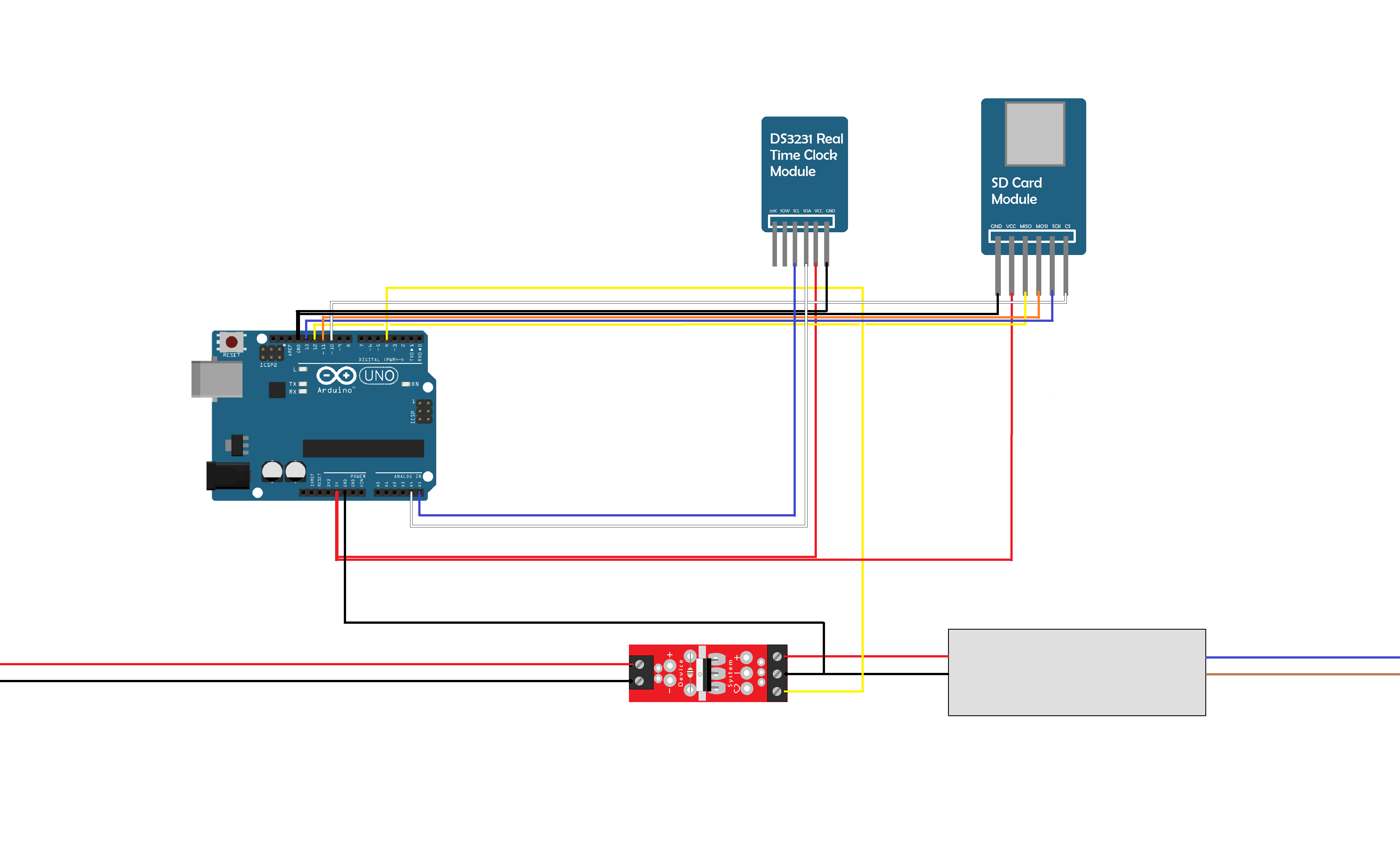
Then, connect the SD card modules and DS3231 real-time clock module to the Arduino Uno. This can be done with jumper wires. A breadboard could also be used to organize the circuit components. The pin connections are outlined in the tables below and illustrated in the following diagram. In addition, connect pin 4 to the gate pin off the SSR. This is also illustrated in the diagram.
Then, download the DS3231 module library from the following link. Upload the code to the Arduino Uno via the USB port. Enter the date, and the hertz at which the light will flash. The flash is set at a 10 percent duty cycle, but this can also be adjusted.
After uploading the code, insert a micro SD card into the SD card module. Then, connect the Arduino power supply to the Arduino Uno, and the main power cord to an AC outlet.
Then It's all ready to go! The light should begin flashing at the designated frequency. I wouldn't run the light for too long though -- the LEDs are seriously powerful, and heat up quickly.


_ztBMuBhMHo.jpg?auto=compress%2Cformat&w=48&h=48&fit=fill&bg=ffffff)


_3u05Tpwasz.png?auto=compress%2Cformat&w=40&h=40&fit=fillmax&bg=fff&dpr=2)
Comments