/*
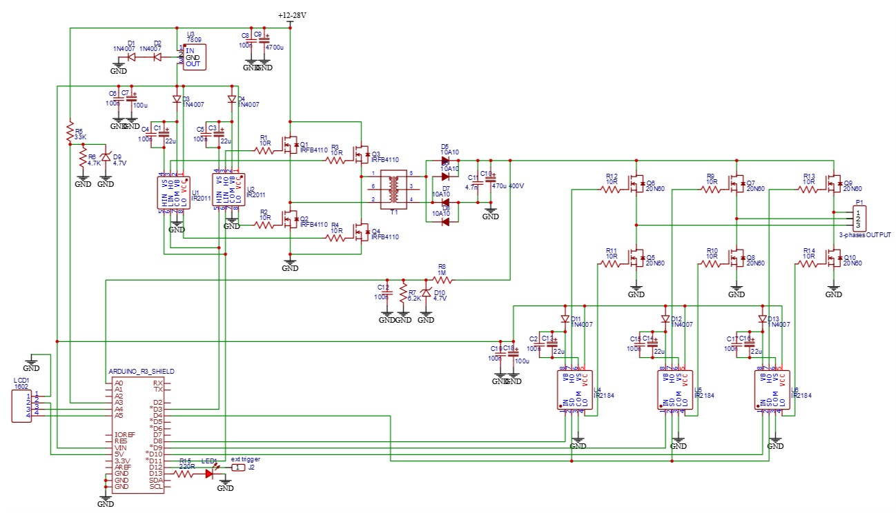
Mini inverter for a 230Vac @ 50Hz from a 12V ro 24 DC, for a power up to 500W.
_________________________________________________________________
| |
| author : Philippe de Craene <dcphilippe@yahoo.fr |
| Free of use - Any feedback is welcome |
_________________________________________________________________
The converter works in 2 parts:
- First the DC input is transformed to 220V/400VDC with a DC-DC converter based on
Timer2 31KHz. Timer2 works with Arduino pins 3 and 11.
- Then the high voltage is cut in a sequence 6x 3.33ms (300Hz x6 = 50Hz) from interrupts set by Timer1,
in order to make 3 phases AC sqare signal. Between 2 phases to result is a pseudo sinus signal, enough for a motor.
PWM mode explanation: https://www.arduino.cc/en/Tutorial/SecretsOfArduinoPWM
Timer 1 register access from: https://github.com/PaulStoffregen/TimerOne
SPWM code from: https://github.com/Irev-Dev/Arduino-Atmel-sPWM
remarks:
--------
The _BV(XXX) function sets the XXX bit of whatever register you are working with to one.
It is defined by the following C macro buried somewhere in the libraries used by the compiler:
#define _BV(bit) (1 << (bit))
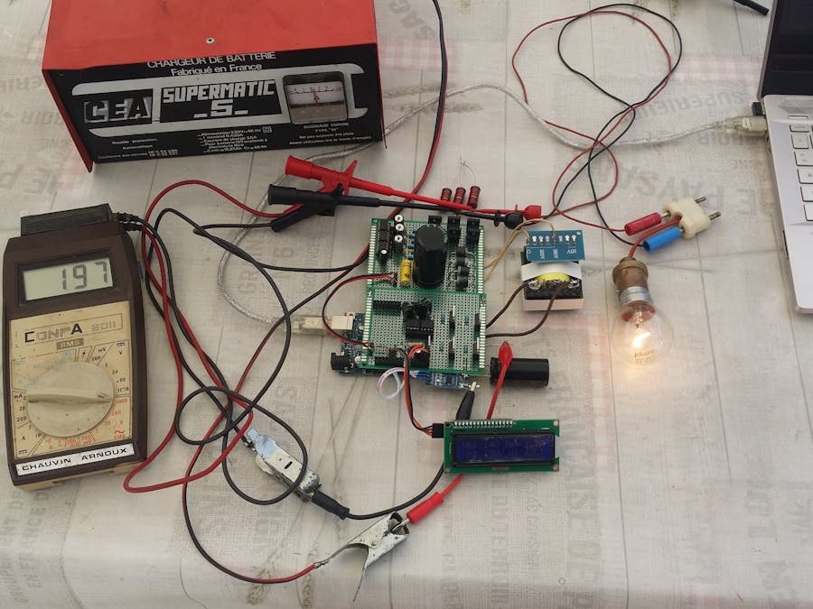
Arduino Uno pinout
------------------
A0 ==> AC output rectified voltage sensor
A1 ==> DC input current sensor ACS712 20A
A2 ==> heatsink temperature sensor LM35
A3 ==> battery input voltage
A4 ==> LCD 1602 SDA
A5 ==> LCD 1602 SCL
4 ==> disable: SD pin of IR2184 (AC output driver)
8 ==> DC to AC phase 1 with IR2184
9 ==> DC to AC phase 2 with IR2184
10 ==> DC to AC phase 3 with IR2184
3 ==> 12VDC to 400VDC with IR2011
11 ==> 12VDC to 400VDC with IR2011
12 ==> synchro output (for oscilloscope external trigger)
13 ==> activity / alarm LED output
Versions history
----------------
version 0.5 - 20 july 2020 - first operational version
version 0.6 - 2 aug 2020 - 50Hz starts once Vht is raised
*/
#include <LiquidCrystal_I2C.h> // https://github.com/fdebrabander/Arduino-LiquidCrystal-I2C-library
#include <TimerOne.h> // https://github.com/PaulStoffregen/TimerOne
// Parameters
//-----------
bool SETUP_MODE = false; // read the Ioffset value needed for 0 current
bool VERBOSE_MODE = true; // set the console display mode
const int Ioffset = 565; // set to get 0 when no current (mid value 0-1023
const float coefVht = 1.26; // calibrate the output 2 phases AC
const float coefVbat = 0.97; // calibrate the input DC voltage
const int microseconds = 3333; // AC period => 3.33ms for 300Hz = 6x 50Hz
const int VhtRef = 200; // 200V DC gives 192V AC
const int deltaVht = 4; // tolerance/hysteresis on Vht
const int VbatMin = 11; // inverter will stop below this input voltage
const int VbatMax = 29; // inverter will stop after this input voltage
bool isThsSensor = false; // is there or not a temperature sensor on IRFB4110 heatsink
const int ThsMax = 70; // heater sink max temperature
bool isIdcSensor = true; // is there or not a current sensor in use
const int IdcMax = 10; // absolute max current from DC input => 10 = 10A
// choose the right current sensor model for ACS712:
//float convI = 185.0; // 5A ACS712 module => 185mV/A
float convI = 100.0; // 20A ACS712 module => 100mV/A
//float convI = 66.0; // 30A ACS712 module => 66mV/A
// Hardware connexion
//-------------------
const byte pp01Pin = 3; // push-pull output 1 for 12VDC / 400VDC converter
const byte pp02Pin = 11; // push-pull output 2 for 12VDC / 400VDC converter
const byte ac1Pin = 8; // DC to AC phase 1
const byte ac2Pin = 9; // DC to AC phase 2
const byte ac3Pin = 10; // DC to AC phase 3
const byte enablePin = 4; // disable/enable AC output, enable to LOW
const byte triggerPin = 12; // ext trigger for oscilloscope
const byte ledPin = 13; // LED for activity and alarm
const byte VhtPin = 0; // analog 0 = output HT transformer sensor
const byte IdcPin = 1; // analog 1 = DC input current sensor ACS712 20A
const byte ThsPin = 2; // analog 2 = heatsink temperature sensor LM35
const byte VbatPin = 3; // analog 3 = input level voltage sensor
// Global variables
//-----------------
int HTduty = 1; // duty cycle for HT converter
const int HTdutyMax = 127; // must be below to 128 according to push-pull/bridge PWM
bool disable = true; // flag for enabling/disabling AC
unsigned int measures = 10; // number of readings for each measure of Vht Idc and Ths
unsigned int displayUpdate = 50; // number of measures cycles for LCD display update
// LCD declaration with I2C
//-------------------------
// set the I2C LCD address to 0x27 for a 16 chars and 2 line display
LiquidCrystal_I2C lcd(0x27, 16, 2);
// => pinup for I2C with Arduino Uno R3 : SDA = A4, SCL = A5
//
// setup
//____________________________________________________________________________________________
void setup() {
// define inputs & outputs
//------------------------
// do not set pinmode for analog entries, otherwise A3 causes a Timer2 error
pinMode( enablePin, OUTPUT ); digitalWrite(enablePin, LOW);
pinMode( ac1Pin, OUTPUT ); digitalWrite(ac1Pin, LOW);
pinMode( ac2Pin, OUTPUT ); digitalWrite(ac2Pin, LOW);
pinMode( ac3Pin, OUTPUT ); digitalWrite(ac3Pin, LOW);
pinMode( pp01Pin, OUTPUT ); digitalWrite(pp01Pin, LOW);
pinMode( pp02Pin, OUTPUT ); digitalWrite(pp02Pin, LOW);
pinMode( triggerPin, OUTPUT );
pinMode( ledPin, OUTPUT);
// LCD initialisation
lcd.begin(); // initialize the lcd for 16 chars 2 lines
lcd.clear();
lcd.setCursor(0, 0);
lcd.print("INVERTER");
lcd.setCursor(0, 1);
lcd.print("is starting !");
// console initialisation
Serial.begin(250000);
Serial.println("Starting....");
// prepare timers
//---------------
// set Timer2 clock divider at 1 for a PWM frequency fixed to 31372.55 Hz
// Arduino Uno pins 3 and 11
// https://etechnophiles.com/change-frequency-pwm-pins-arduino-uno/
TCCR2B = _BV(CS10); // set clock at 31KHz
TCCR2A = _BV(COM2A1) // set non-inverting pp01Pin output 3
| _BV(COM2B1) // set non-inverting pp02Pin output 11
| _BV(COM2B0) // set inverting mode on
| _BV(WGM20); // fast PWM
OCR2A = HTduty; // set duty cycle <126 to prevent against both side continuity
OCR2B = 255 - HTduty; // the inverting ratio
// set Timer1 for an interrupt every 3333us
Timer1.initialize(microseconds);
Timer1.attachInterrupt(ACgenerate);
} // end of setup
//
// loop
//____________________________________________________________________________________________
void loop() {
float Idc; // DC input current
int Vbat, Vht, Ths; // Input voltage, HT output rectified voltage, heatsink temperature
static long cumulIdc = 0; // cumulative input DC current sensor
static long cumulVbat = 0; // cumulative input DC voltage sensor
static long cumulVht = 0; // cumulative output AC voltage sensor
static long cumulThs = 0; // cumulative heatsink temperature sensor
static int counter = 0; // cycles counter
static int counter2 = 0; // measures counter
// Idc DC input current sensor reading with overcurrent security
if( isIdcSensor ) {
Idc = analogRead(IdcPin); // 0 to 1023 in bytes for -20A to 20A, 512 in bytes =0A
delayMicroseconds(100);
if( Idc < 2 || Idc > 1022 ) { // reading in bytes
ACenable(2); // stop AC
return; // nothing else is done
}
} // end of test isIdcSensor
else Idc = Ioffset; // if no current sensor
// Vbat input volatge & Vht transformer output & Ths temperature reading
Vbat = analogRead(VbatPin); delayMicroseconds(100);
Vht = analogRead(VhtPin); delayMicroseconds(100);
if( isThsSensor ) { Ths = analogRead(ThsPin); delayMicroseconds(100); }
else Ths = 0;
// perform cumulative readings to improve accurancy against noises
cumulIdc += Idc;
cumulVbat += Vbat;
cumulVht += Vht;
cumulThs += Ths;
if( ++counter > measures ) { // after 'measures' number we go in sensors reading cycles
counter = 0;
counter2 ++;
if( !SETUP_MODE ) Idc = (((cumulIdc/measures) - Ioffset) *2500.0/convI/1023.0);
else Idc = (cumulIdc/measures);
if( Idc < 0 ) Idc = -Idc; // input DC current positive whenever the sensor connection
Vbat = (float)((cumulVbat/measures) *coefVbat*39.0/1023.0); // input voltage
Vht = (float)((cumulVht/measures) *coefVht*500.0/1023.0); // output HT voltage
Ths = (cumulThs/measures) *500/1023; // temperature in degrees Celsius
cumulVbat = 0;
cumulVht = 0;
cumulIdc = 0;
cumulThs = 0;
} // end of test counter
// what is done every time measures are completed
if( counter != 0 ) return; // everything after is done when counter = 0
// manage HTduty to get the 'VhtRef' output voltage
if( Vht < (VhtRef - deltaVht)) {
if( ++HTduty > HTdutyMax ) HTduty = HTdutyMax;
}
else if( Vht > (VhtRef + deltaVht)) {
if( --HTduty < 0 ) HTduty = 0;
}
// verify normal working conditions
if( Idc > IdcMax ) ACenable(3);
else if( Vbat < VbatMin ) ACenable(4);
else if( Vbat > VbatMax ) ACenable(5);
else if( Ths > ThsMax ) ACenable(6);
else if( Vht < (3*VhtRef/4)) ACenable(1);
else ACenable(0); // allow inverter pseudo sinus output
// set the PWM
OCR2A = HTduty; // set duty cycle
OCR2B = 255 - HTduty; // the inverting ratio
// LCD 1602 display management
if( counter2 > displayUpdate ) {
counter2 = 0;
lcd.setCursor(0, 0);
lcd.print("Vb: ");
if( Vbat < 10 ) lcd.print(" ");
lcd.print(Vbat);
lcd.setCursor(6, 0);
lcd.print("V Ib: ");
if( Idc < 10.0 ) lcd.print(Idc,1);
else lcd.print(Idc,0);
lcd.print("A");
if( !disable ) {
lcd.setCursor(0, 1);
lcd.print("Vs: ");
if( Vht < 100 ) lcd.print(" ");
lcd.print(Vht);
lcd.setCursor(7, 1);
lcd.print("V d: ");
int val = map( HTduty, 1, HTdutyMax, 0, 99 );
if( val < 10 ) lcd.print(" ");
lcd.print(val);
lcd.print("%");
}
}
// console monitoring
if( VERBOSE_MODE ) {
Serial.print(" Vbat= "); Serial.print(Vbat);
Serial.print("\t Vht= "); Serial.print(Vht);
Serial.print("\t Idc= "); Serial.print(Idc);
Serial.print("\t Ths= "); Serial.print(Ths);
Serial.print("\t HTduty= "); Serial.print(HTduty);
Serial.print("\t disable= "); Serial.print(disable);
Serial.println();
}
} // end of loop
//============================================================================================
// list of functions
//============================================================================================
//
// ACenable() : allow AC or display error message
//____________________________________________________________________________________________
void ACenable( byte reason ) {
if( reason == 0 ) {
if( disable ) {
for( byte i=0; i<3; i++ ) {
digitalWrite(ledPin, HIGH); delay(10);
digitalWrite(ledPin, LOW); delay(300);
}
digitalWrite(enablePin, HIGH); // enable AC
disable = false; // so that this is run once
} // end of test disable == true
} // end of test reason == 0
else if( reason == 1 ) {
digitalWrite(enablePin, LOW); // disable AC
disable = true;
lcd.setCursor(0, 1); lcd.print("! waiting for HT!");
}
else {
HTduty = 0; // stop the high volatge
digitalWrite(ledPin, HIGH); // alarm LED always on
disable = true;
switch( reason ) {
case 2: lcd.setCursor(0, 1); lcd.print("! short circuit!"); break;
case 3: lcd.setCursor(0, 1); lcd.print("! overcurrent !"); break;
case 4: lcd.setCursor(0, 1); lcd.print("! low battery !"); break;
case 5: lcd.setCursor(0, 1); lcd.print("! high battery !"); break;
case 6: lcd.setCursor(0, 1); lcd.print("! over heating !"); break;
default: lcd.setCursor(0, 1); lcd.print("! other error !"); break;
} // end of switch
} // end of else
} // end of EnableAC()
//
// ACgenerate() : function to create the 3 phase AC
//____________________________________________________________________________________________
void ACgenerate() {
static byte cycle = 0;
static bool trigger = false;
switch( cycle ) {
case 0: digitalWrite(ac1Pin, HIGH); digitalWrite(ac2Pin, LOW); digitalWrite(ac3Pin, HIGH); break;
case 1: digitalWrite(ac1Pin, HIGH); digitalWrite(ac2Pin, LOW); digitalWrite(ac3Pin, LOW); break;
case 2: digitalWrite(ac1Pin, HIGH); digitalWrite(ac2Pin, HIGH); digitalWrite(ac3Pin, LOW); break;
case 3: digitalWrite(ac1Pin, LOW); digitalWrite(ac2Pin, HIGH); digitalWrite(ac3Pin, LOW); break;
case 4: digitalWrite(ac1Pin, LOW); digitalWrite(ac2Pin, HIGH); digitalWrite(ac3Pin, HIGH); break;
case 5: digitalWrite(ac1Pin, LOW); digitalWrite(ac2Pin, LOW); digitalWrite(ac3Pin, HIGH); break;
} // end of switch
if( ++cycle >5 ) {
cycle = 0;
//digitalWrite(triggerPin, trigger);
//trigger = !trigger;
}
} // end of ACgenerate()


_ztBMuBhMHo.jpg?auto=compress%2Cformat&w=48&h=48&fit=fill&bg=ffffff)


Comments