

Hardware components | ||||||
_ztBMuBhMHo.jpg?auto=compress%2Cformat&w=48&h=48&fit=fill&bg=ffffff) |
| × | 1 | |||
 |
| × | 2 | |||
 |
| × | 2 | |||
 |
| × | 2 | |||
| × | 1 | ||||
 |
| × | 1 | |||
Software apps and online services | ||||||
 |
| |||||
Hand tools and fabrication machines | ||||||
 |
| |||||
 |
| |||||
For those who have a wind turbine in their garden, one of the worst thing that can happen is to see the propeller smoothy turn and turn and suddenly stop for a very short time and then turn again, without apparently any reason to stop. What has happened ????
May be it is the 3-wires cable that has a short circuit.... How to see ? With a voltmeter of course, you can verify... but most of time you will only measure that everything is right. Because of course the short-circuit is very brief, very short.
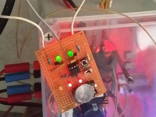
Here is a solution : when installed, if everything is all right the 2 red leds are off. But as soon as no voltage is detected between 2 of the 3 wires (or the 3 wires) one led will flash which indicates which wire has a problem :
Red led 1 if there is a problem between volt1 and volt3, red led 2 if there is a problem between volt2 and volt3, both red led indicates a problem between volt2 and volt3, or, that there is no more wind....
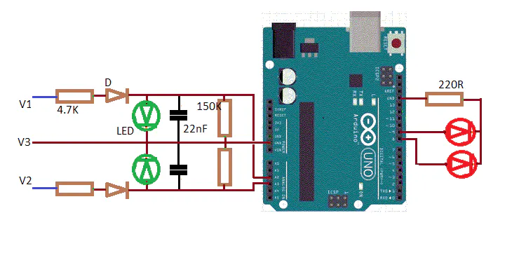
R is set to limit current : 4.7K will make a current of 10mA for a voltage of 47V, and 20mA for 94V.
D is a rectifier diode, like 1N4001 or whatever you want.
LED (green led ) acts as a zener to limit the input voltage to the analog input of the Arduino. I use a years 90 green led that has its working voltage arround 2V. You can use whatever LED you wish, at the condition its working voltage is under 2.5V if used with the ATtiny85.
What does the code perform ?
It continuously reads the volt1 and volt2 voltage for 100 cycles. Don't forget it is AC voltage, so a little time is needed to insure to get several periods of the voltage. If after this time the value is too low, then it stops the measures and the right red led is flashing, until a reset. At the same time a comparison is done between volt1 and volt2, if measured values are too near, both red leds are flashing.
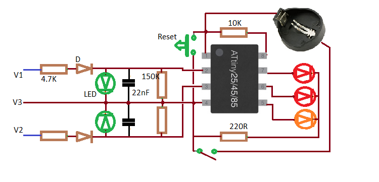
The code is proposed for Arduino, and ATtiny85.
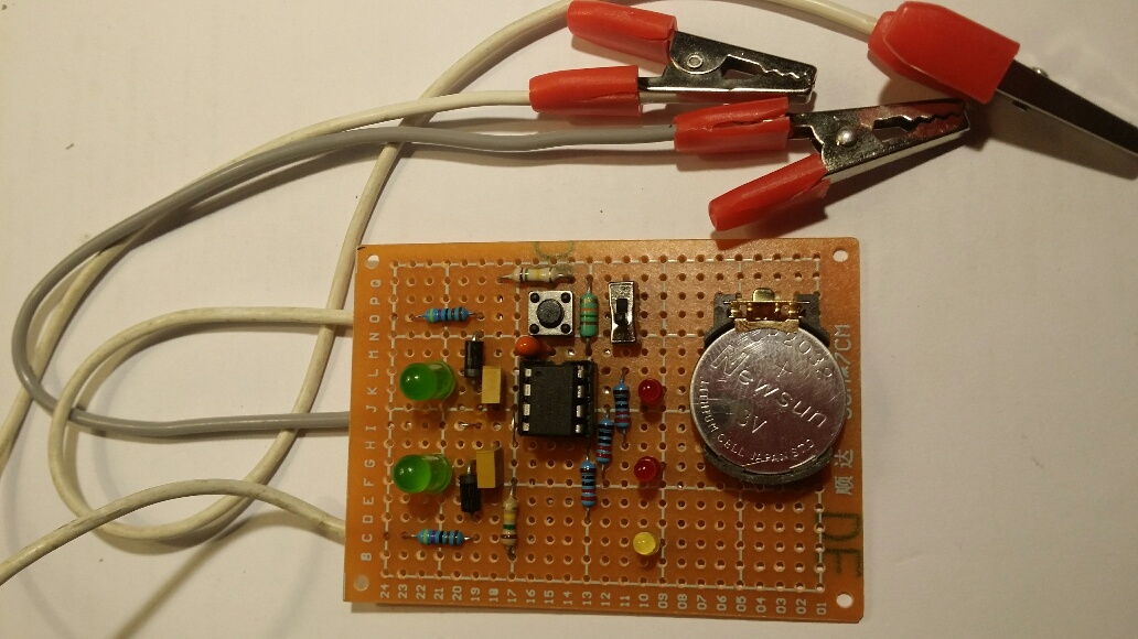
The advantage of the ATtiny85 is very small, so it is possible to build a very small size device that can operate under 3V with a CR2032 cell. Thanks to the sleeping method in the code that will insure the cell will operate for years !


Comments