

Hardware components | ||||||
_ztBMuBhMHo.jpg?auto=compress%2Cformat&w=48&h=48&fit=fill&bg=ffffff) |
| × | 1 | |||
 |
| × | 2 | |||
 |
| × | 1 | |||
 |
| × | 3 | |||
Software apps and online services | ||||||
 |
| |||||
Hand tools and fabrication machines | ||||||
 |
| |||||
If you have a wind turbine, it will need a regulator. All regulator has two goals:
- To protect the wind turbine against over speed of the turbine that may destroy it.
- To adapt the power delivered to charge a battery or to drive an injector.
There are many regulators on the market. However they are mostly adapted for solar panels only, and if the curve of delivered power is similar, the way to regulate is different – to resume solar panels use buck converter, wind turbines use boost converter. Many are not MPPT, the PWM regulators are very less efficient than MPPT, and also specific wind turbine MPPT regulators are very expensive.
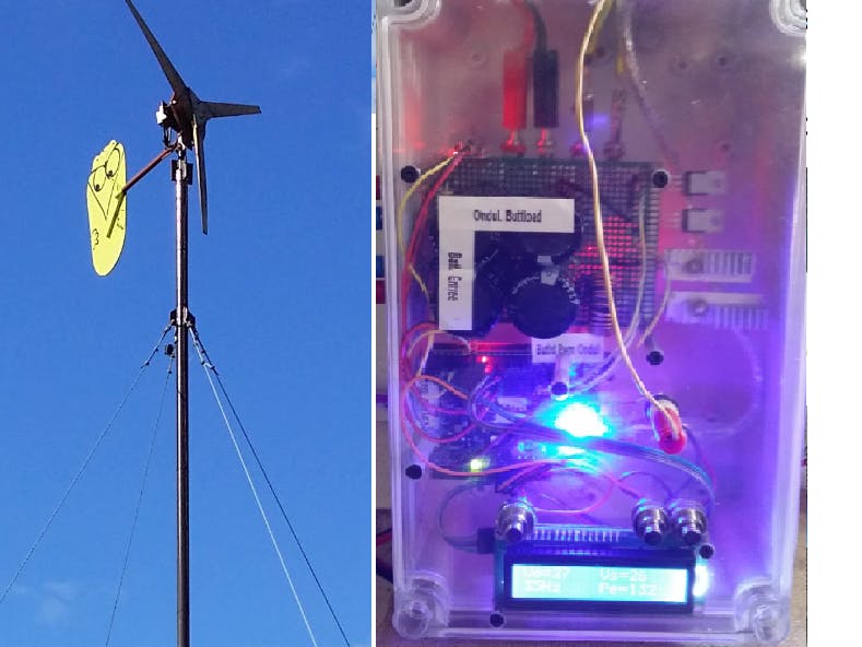
So, It can be a very good project to self-build our own regulator, after having been built our own Piggott wind turbine. :-)
Update : v2 include a PCB and 12V wind turbine

regulateur_boost_MPPT-v2.0.ino
ArduinoHere is the Arduino code V2 for the Wind Turbine MPPT Regulator for Arduino Uno or ATmega328p
/*
Wind Turbine MPTT Regulator, for direct injection or battery charging
_________________________________________________________________
| |
| author : Philippe de Craene <dcphilippe@yahoo.fr |
| Free of use - Any feedback is welcome |
_________________________________________________________________
Materials :
1* Arduino Uno R3 - IDE version 1.8.7
2* 20A current sensor ACS712 modules
2* Power MOSFET drivers TC428
1* LCD 1602 with I2C extension
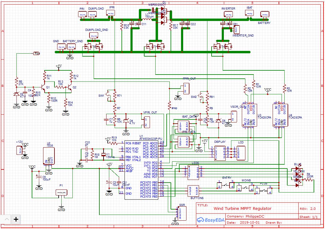
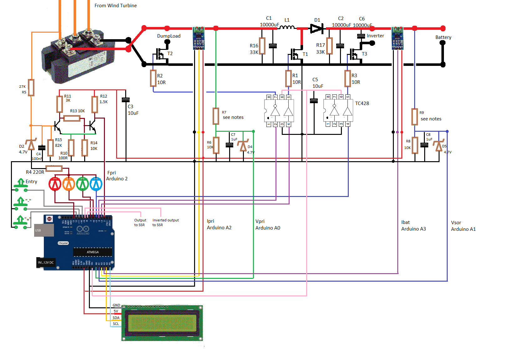
1 DC-DC boost converter : PCB is proposed for the use of a DIP28 Atmega328p
Arduino Uno pinup (with Atmega328p matching:
input voltage sensor : VpriPin => input A0 = ADC0
output voltage sensor : VsorPin => input A1 = ADC1
input current sensor : IpriPin => input A2 = ADC2
battery current sensor : IbatPin => input A3 = ADC4
SDA for I2C LCD : SDA => output A4 = ADC4
SCL for I2C LCD : SCD => output A5 = ADC5
wind turbine speed : FpriPin => input 2 = PD2
driving PWM signal : gatePin => output 3 = PD3 - DC-DC converter driver signal
dumpload signal : loadPin => output 4 = PD4 - dumpload resistor
inverter enable signal : ondulPin => output 5 = PD5 - blue LED + inverter
limit MPPT indicator : limitPin => output 6 = PD6 - yellow LED (!!! pin8 in V1.x!!!)
MPPT indicator : mpptPin => output 7 = PD7 - green LED
external charger : ssrN_Pin => output 8 = PB0 - Normal output to SSR
external charger : ssrI_Pin => output 9 = PB1 - Inverted output to SSR
"ok" push button : pbE_Pin => output 10 = PB2
"-" push button : pbM_Pin => output 11 = PB3
"+" push button : pbP_Pin => output 12 = PB4
overhead alarm : alarmPin => output 13 = PB5 - red LED (!!! pin9 in V1.x!!!)
Versions history :
version 0.4 - 26 march 2019 - Fpri sensor rebuild with interrupt function
version 0.5 - 27 march 2019 - Ipri sensor rebuild for average value
version 0.6 - 26 april 2019 - MPPT algorithm rebuild without Fpri
version 0.7 - 27 april 2019 - DC-DC converter rebuilt from buck-boost inverter to boost
version 1.0 - 2 june 2019 - First full working version
version 1.1 - 5 july 2019 - added EEPROM and menus
version 1.2 - 5 july 2019 - improvment of the display of voltages
version 1.3 - 13 july 2019 - improvment of security underload and overload and Ibat measure
version 1.4 - 8 oct 2019 - new LiquidCrystal-I2C-library and direct injection bug correction
version 2.0 - 9 oct 2019 - update for PCB
*/
#include <EEPROM.h> // EEPROM to keep redifined parameters data
#include <LiquidCrystal_I2C.h> // https://github.com/fdebrabander/Arduino-LiquidCrystal-I2C-library
const bool VERBOSE = true;//false; // if true : debugging mode => very slow !
const bool REGLAGE = false; // if true : for current sensor offset settings
bool USAGE_FPRI = true; // if true : the turbine speed is calculated
bool mode_injection = false; // if true : direct injection : no batteries needed
// Wind turbine voltage model : 24 ou 48V
// VpriMax is twice the optimal wind turbine voltage :
// a 24V wind turbine can reach 50V => VpriMaxRef = 50.0V
// a 48V wind turbine can reach 100V => VpriMaxRef = 100.0V
int VpriMaxRef = 50; // 24V model
int VpriMax = 31; // MAx value until DumpLoad Resistor security
// Current sensor model for ACS712 :
// 5A ACS712 module => 185mV/A
// 20A ACS712 module => 100mV/A
// 30A ACS712 module => 66mV/A
const float convI = 100.0; // 20A model (float number is required)
// Depending of the way the ACS712 module is wired, polarity ajustment may be required
// to get the charging batteries current positive, values can be 1 or -1
const int IbatPolarity = 1;
// General parameters
const int Ioffset = 510; // offset is set with REGLAGE = true, to get Ipri=0 with no current (~512)
const byte pwm_gate_Max = 220; // Max PWM allowed (<250)
int IbatMax = 15; // must be = 0,23 time the battery capacity => 13A for 54Ah
int VpriMin = 15; // the voltage that will start the MPPT process. Too low the wind turbine may have difficulties to start
int Vsor_calibrate = 100; // to adjust Vsor to match real value with multimeter 100 = 100%
// Battery mode parameters (floats numbers)
float VsorMin = 24.0; // discharged battery voltage : see battery datasheet for exact value
float VsorFlo = 26.6; // floating voltage : see battery datasheet for exact value
float VsorMax = 29.8; // maximum voltage : see battery datasheet for exact value
// Direct injection parameters (int numbers)
byte VsorMin_injection = 23; // see inverter datasheet for correct values
byte VsorFlo_injection = 28; // injection will start over the "floating value"
byte VsorMax_injection = 59; // and will stop under the "Min value"
/// inputs outputs declaration
#define VpriPin A0 // input to Vpri sensor
#define VsorPin A1 // input to Vsor sensor
#define IpriPin A2 // input to Ipri sensor
#define IbatPin A3 // input to Ibat sensor
#define FpriPin 2 // input to Fpri sensor
#define gatePin 3 // pwm output to drive the DC-DC converter circuit (pwm_gate)
#define loadPin 4 // inverted output (because of TC428) dumpload resistor
#define ondulPin 5 // output inverter enabling
#define limitPin 6 // output to yellow LED
#define mpptPin 7 // output to green LED
#define ssrN_pin 8 // output for SSR for external battery charger
#define ssrI_pin 9 // inverted output for external battery charger
#define pbE_Pin 10 // push-button for parameters access
#define pbM_Pin 11 // push-button -
#define pbP_Pin 12 // push-button +
#define alarmPin 13 // output to red LED
// variables for treatment
float Vpri, memo_Vpri, Vsor; // input and output voltage
float Ipri, Ibat; // input and battery current
float Puiss = 0, memo_Puiss; // input power
unsigned int Fpri = 0; // turbine speed in Hertz
int kept_VpriMax = 0; // Max measured Vpri for display
int kept_IpriMax = 0; // Max measured Ipri for display
int kept_PuissMax = 0; // Max calculated Puiss for display
int kept_FpriMax = 0; // Max measured Fpri for display
unsigned int lect_Ipri_count = 0; // number of Ipri measures
unsigned long somme_lect_Ipri = 0; // Ipri measures added between two interrupts (in bytes)
unsigned long somme_lect_Ibat = 0; // Ibat measures added between two interrupts (in bytes)
volatile bool Fpri_flag = false; // Fpri flag interruption
unsigned int Fpri_tempo = 0, memo_Fpri_tempo, duration; // time spent for Fpri measure
int Step = 0; // pwm ratio update for pwm_gate
int pwm_gate = 0; // pwm signal command for DC-DC converter
byte VsorMinInt, VsorMinDec, VsorFloInt, VsorFloDec, VsorMaxInt, VsorMaxDec;
byte overflow_count = 0; // count any averflow cycle
// variables for display and menus
unsigned int memo_tempo = 0; // time flag when Fpri=0
unsigned int memo_tempo_LCD = 0; // time flag for LCD refresh
unsigned int refresh_tempo = 1000; // refresh delay for LCD update
bool pbM, memo_pbM, pbP, memo_pbP;
byte ret_push_button = 0;
byte window = 0;
byte count_before_timeout = 0;
byte timeout = 20;
// LCD with I2C declaration :
// documentation : http://arduino-info.wikispaces.com/LCD-Blue-I2C
// Set the pins on the I2C chip used for LCD connections:
// addr, en,rw,rs,d4,d5,d6,d7,bl,blpol
LiquidCrystal_I2C lcd(0x27, 16, 2);
// => Arduino Uno R3 pin connexion : SDA to A4, SCL to A5
//
// SETUP
//_____________________________________________________________________________________________
void setup() {
// inputs outputs declaration
pinMode(VpriPin, INPUT); // input for Vpri sensor - input voltage
pinMode(VsorPin, INPUT); // input for Vsor sensor - output voltage
pinMode(IpriPin, INPUT); // input for Ipri sensor - input current
pinMode(IbatPin, INPUT); // input for Ibat sensor - battery current
pinMode(FpriPin, INPUT); // input for Fpri sensor - turbine speed
pinMode(gatePin, OUTPUT); // pwm output pwm_gate
pinMode(loadPin, OUTPUT); // inverted output for dumpload resistor
pinMode(ondulPin, OUTPUT); // output for enabling injection
pinMode(mpptPin, OUTPUT); // output to green LED
pinMode(limitPin, OUTPUT); // output to yellow LED
pinMode(alarmPin, OUTPUT); // output to red LED
pinMode(ssrN_pin, OUTPUT); // output for SSR for external battery charger
pinMode(ssrI_pin, OUTPUT); // inverted output for external battery charger
pinMode(pbE_Pin, INPUT_PULLUP); // push-button for menus acces
pinMode(pbM_Pin, INPUT_PULLUP); // push-button -
pinMode(pbP_Pin, INPUT_PULLUP); // push-button +
// outputs initialisation for no signal
analogWrite(gatePin, 0);
digitalWrite(loadPin, HIGH); // with MOSFET driver circuit TC428 pin 7 output is inverted
digitalWrite(ondulPin, LOW); // with MOSFET driver circuit TC428 pin 5 output is non-inverted
digitalWrite(ssrN_pin, LOW); // output for SSR for external battery charger
digitalWrite(ssrI_pin, HIGH); // inverted output for external battery charger
// EEPROM check and data upload :
// stored data are always positive from 0 to 255.
// it seems that in cas of first use all are set to 255.
if (EEPROM.read(0) < 2) USAGE_FPRI = EEPROM.read(0); else EEPROM.write(0, USAGE_FPRI);
if (EEPROM.read(1) < 2) mode_injection = EEPROM.read(1); else EEPROM.write(1, mode_injection);
if (EEPROM.read(2) < 131) VpriMax = EEPROM.read(2); else EEPROM.write(2, VpriMax);
if (EEPROM.read(3) < 51) VpriMin = EEPROM.read(3); else EEPROM.write(3, VpriMin);
if (EEPROM.read(4) < 41) IbatMax = EEPROM.read(4); else EEPROM.write(4, IbatMax);
VsorMinInt = VsorMin;
VsorMinDec = 10 * (VsorMin - VsorMinInt);
VsorFloInt = VsorFlo;
VsorFloDec = 10 * (VsorFlo - VsorFloInt);
VsorMaxInt = VsorMax;
VsorMaxDec = 10 * (VsorMax - VsorMaxInt);
if (EEPROM.read(5) < 65) VsorMinInt = EEPROM.read(5); else EEPROM.write(5, VsorMinInt);
if (EEPROM.read(6) < 100) VsorMinDec = EEPROM.read(6); else EEPROM.write(6, VsorMinDec);
if (EEPROM.read(7) < 65) VsorFloInt = EEPROM.read(7); else EEPROM.write(7, VsorFloInt);
if (EEPROM.read(8) < 100) VsorFloDec = EEPROM.read(8); else EEPROM.write(8, VsorFloDec);
if (EEPROM.read(9) < 131) VsorMaxInt = EEPROM.read(9); else EEPROM.write(9, VsorMaxInt);
if (EEPROM.read(10) < 100) VsorMaxDec = EEPROM.read(10); else EEPROM.write(10, VsorMaxDec);
if (EEPROM.read(11) < 65) VsorMin_injection = EEPROM.read(11); else EEPROM.write(11, VsorMin_injection);
if (EEPROM.read(12) < 100) VsorFlo_injection = EEPROM.read(12); else EEPROM.write(12, VsorFlo_injection);
if (EEPROM.read(13) < 200) VsorMax_injection = EEPROM.read(13); else EEPROM.write(13, VsorMax_injection);
if ( mode_injection == true ) {
VsorMin = VsorMin_injection;
VsorFlo = VsorFlo_injection;
VsorMax = VsorMax_injection;
}
else {
VsorMin = 1.0 * VsorMinInt + (1.0 * VsorMinDec) / 10.0;
VsorFlo = 1.0 * VsorFloInt + (1.0 * VsorFloDec) / 10.0;
VsorMax = 1.0 * VsorMaxInt + (1.0 * VsorMaxDec) / 10.0;
}
if (EEPROM.read(14) < 120) Vsor_calibrate = EEPROM.read(14); else EEPROM.write(14, Vsor_calibrate);
// Set clock divider for timer 2 at 1 = PWM frequency of 31372.55 Hz
// Arduino Uno R3 pins 3 and 11
// https://etechnophiles.com/change-frequency-pwm-pins-arduino-uno/
TCCR2B = TCCR2B & 0b11111000 | 0x01;
attachInterrupt(digitalPinToInterrupt(FpriPin), Fpri_detect, RISING);
// Every state update from down to up of FpripPin the function 'Fpri_detect' is called
// documentation : https://www.arduino.cc/reference/en/language/functions/external-interrupts/attachinterrupt/
// Console initialisation
Serial.begin(250000);
Serial.println();
Serial.println("Ready to start...");
if( VERBOSE == true ) Serial.println("Verbose mode");
if( REGLAGE == true ) Serial.println("Current offset mode");
Serial.println();
// LCD initialisation
lcd.begin(); // initialize the lcd for 16 chars 2 lines
lcd.clear();
lcd.setCursor(0, 0);
lcd.print(" Wind Turbine ");
lcd.setCursor(0, 1);
lcd.print(" MPPT regulator ");
delay(1000);
lcd.clear();
} // fin de setup
//
// Fpri_detect : what is done at each interruption
//____________________________________________________________________________________________
void Fpri_detect() {
Fpri_flag = true;
}
//
// LOOP
//_____________________________________________________________________________________________
void loop() {
unsigned int tempo = millis(); // time count
int lect_Ipri = analogRead(IpriPin);
delayMicroseconds(100);
int lect_Ibat = analogRead(IbatPin);
delayMicroseconds(100);
// overcurrent security
//_______________________________________________
if( lect_Ipri < 1 || lect_Ipri > 1022 ) { // reading in bytes
analogWrite(gatePin, 0); // no driving control to MPPT
digitalWrite(alarmPin, HIGH);
return; // nothing else is done
}
// cumulative Ipri and Ibat measures between 2 interupts = one turbine rotation
somme_lect_Ipri += lect_Ipri;
delayMicroseconds(100);
somme_lect_Ibat += lect_Ibat;
delayMicroseconds(100);
lect_Ipri_count++;
// Every turbine period, or every second if no wind, or every 100ms is Fpri not measured
//_______________________________________________
if( (USAGE_FPRI == true && (Fpri_flag == true || tempo - memo_tempo > 1000))
|| (USAGE_FPRI == false && tempo - memo_tempo > 100) ) {
noInterrupts(); // disable any possible interruption
Fpri_flag = false; // flag reset, will be ready to be set at next interrupt
memo_tempo = tempo;
memo_Puiss = Puiss; // memorization of the previous Puiss measurement
memo_Vpri = Vpri; // memorization of the previous Vpri measurement
// Measures and calculation of power values
//_______________________________________________
// time spent between 2 interrupts => Fpri calculation
memo_Fpri_tempo = Fpri_tempo; // memorization of the previous time measurement
Fpri_tempo = tempo; // memorization of the actual time measurement
duration = Fpri_tempo - memo_Fpri_tempo;
if ( duration < 1001 ) Fpri = 1000 / duration; // in Hertz = number of rotations/seconde
else Fpri = 0; // set Fpri = 0 if delay over 1s
// analogRead measures are in bits : from 0 to 1023, to convert to :
// -> voltage from 0 to VpriMaxRef for Vpri and Vsor
// -> current : 511 in bits is the 0mA, 0 in bits matches -Imax, 1023 matches +Imax
Vpri = (analogRead(VpriPin) / 1023.0) * VpriMaxRef; // Vpri measure
delayMicroseconds(100);
Vsor = (analogRead(VsorPin) / 512.0) * VpriMaxRef * (Vsor_calibrate / 100.0); // Vsor measure
delayMicroseconds(100);
Ipri = ((float)(somme_lect_Ipri / lect_Ipri_count) - Ioffset) * 5000 / convI / 1023.0; // the average value of Ipri
somme_lect_Ipri = 0; // reset of the counter of the number of measures of Ipri
if ( Ipri < 0 ) Ipri = -Ipri; // to be sure to get a positive value despite the way of wiring
Ibat = ((float)(somme_lect_Ibat / lect_Ipri_count) - Ioffset) * 5000 * IbatPolarity / convI / 1023.0;
somme_lect_Ibat = 0; // reset of the counter of the number of measures of Ipri
lect_Ipri_count = 0;
Puiss = Vpri * Ipri;
// keep the maximum measured values for display only
if ( Vpri > kept_VpriMax ) kept_VpriMax = Vpri;
if ( Ipri > kept_IpriMax ) kept_IpriMax = Ipri;
if ( Puiss > kept_PuissMax ) kept_PuissMax = Puiss;
if ( Fpri > kept_FpriMax && Fpri < 100 ) kept_FpriMax = Fpri;
// setup of the MPPT algorithm
//_______________________________________________
// 2 ways that make a lower power :
// either the wind turbine runs too fast, Vpri increases, so 'step' increases to increase the current (and so Vpri may decrease)
// either less wind, Vpri decreases, so 'step' decreases to decreases the current (and so Vpri may increase)
if ( memo_Vpri <= Vpri ) {
if ( Puiss <= memo_Puiss ) Step = 1;
else Step = -1;
}
else {
if ( Puiss <= memo_Puiss ) Step = -1;
else Step = 1;
}
// Management of DC-DC converter cutting control
//_______________________________________________
if ( Vpri < VpriMin ) { // lower limit input voltage value reached
Step = Step - 10; // sharp decline of step to try to increase Vpri
digitalWrite(mpptPin, LOW); // green LED is OFF
digitalWrite(limitPin, LOW);
digitalWrite(ondulPin, LOW);
}
else if ( Vsor < VsorMin) { // lower limit output volatge
digitalWrite(ondulPin, LOW); // lower limit output voltage value reached
if ( Step < 0 ) {
Step = -Step; // 'Step' is forced to be positive
digitalWrite(limitPin, HIGH); // yellow LED is ON
}
}
else {
digitalWrite(limitPin, LOW);
digitalWrite(mpptPin, HIGH);
if ( Vsor > VsorFlo ) digitalWrite(ondulPin, HIGH); // inverter is ON as soon as VsorFloat is reached
}
if ( Ibat > IbatMax && Step > 0 ) Step = -Step; // 'Step' is forced to be negative
// Overcharge security & pwm ratio update
//_______________________________________________
if ( Vsor > VsorMax ) {
Step = Step - 10; // decrease pwm ratio
overflow_count++; // count the number of overfolw cycles
digitalWrite(alarmPin, HIGH); // red LED is ON
if ( overflow_count > 5 ) { // after 5 cycles of overflow
pwm_gate = -10; // cutting control is stopped
digitalWrite(loadPin, LOW); } // dumpload is ON - remember that TC428 pin 7 is inverted
}
else {
digitalWrite(loadPin, HIGH); // dumpload is OFF
digitalWrite(alarmPin, LOW); // red LED is OFF
overflow_count = 0; // reset the overflow cycles count
}
// constrain the pwm ratio
pwm_gate += Step;
if ( pwm_gate > pwm_gate_Max ) pwm_gate = pwm_gate_Max; // high value limit
else if ( pwm_gate < 0 ) pwm_gate = 0; // low value limit
analogWrite(gatePin, pwm_gate); // cutting command update before any dumpload evaluation
interrupts(); // interrupts enable again
/*
// for debugging purpose only
if ( VERBOSE == true ) {
Serial.print("Fpri= "); Serial.print(Fpri);
Serial.print(" Vpri= "); Serial.print(Vpri);
Serial.print(" Ipri= "); Serial.print(Ipri);
Serial.print(" Puiss= "); Serial.print(Puiss);
Serial.print(" Puiss-memo_Puiss= "); Serial.print(Puiss - memo_Puiss);
Serial.print(" Step : "); Serial.print(Step);
Serial.print(" pwm_gate : "); Serial.print(pwm_gate);
Serial.print(" Vsor= "); Serial.print(Vsor);
Serial.print(" Ibat= "); Serial.print(Ibat);
Serial.println();
}*/
} // end of Fpri 1 period cycle
/*
if ( REGLAGE == true ) {
Serial.print("valeur de I=0 en bits : ");
Serial.print(analogRead(IpriPin) - Ioffset);
Serial.println();
}*/
// LCD and menus management + ext battery charger
//_______________________________________________
// every seconds look for push-button activity and update display
if ( tempo - memo_tempo_LCD > refresh_tempo ) {
memo_tempo_LCD = tempo;
ret_push_button = push_button(); // reading push-button status here only
lcd.setCursor(0, 0);
count_before_timeout++;
if ( count_before_timeout > timeout ) lcd.noBacklight();
if ( ret_push_button == 1 ) {
if ( window != 4 ) next_window();
else {
window = 0;
lcd.clear();
}
}
if ( mode_injection == true && window == 7 ) window++;
// usual display with 2 choises : window 0 and window 1
if ( window < 2 ) {
lcd.print("Ve=");
lcd.print(String(Vpri, 1));
lcd.setCursor(9, 0);
lcd.print("Vs=");
lcd.print(String(Vsor, 1));
lcd.setCursor(0, 1);
if ( window == 0 ) {
if ( USAGE_FPRI == true ) {
lcd.print(Fpri);
lcd.print("Hz");
}
lcd.setCursor(8, 1);
lcd.print("Pe=");
lcd.print(String(Puiss, 1));
}
else if ( window == 1 ) {
lcd.print("Ie=");
lcd.print(String(Ipri, 1));
lcd.setCursor(9, 1);
lcd.print("Ib=");
lcd.print(String(Ibat, 1));
}
} // end of usual display
else {
// if window >= 2 we are entering in max values display and parameters setup
if ( count_before_timeout > timeout ) { // timeout to return to usual display if no job done
count_before_timeout = 0;
window = 0;
lcd.clear();
}
if ( window == 2 ) {
lcd.print("VM=");
lcd.print(kept_VpriMax);
lcd.setCursor(9, 0);
lcd.print("IM=");
lcd.print(kept_IpriMax);
lcd.setCursor(0, 1);
if ( USAGE_FPRI == true ) {
lcd.print(kept_FpriMax);
lcd.print("Hz");
}
lcd.setCursor(8, 1);
lcd.print("PM=");
lcd.print(kept_PuissMax);
} // end of window 2
if ( window == 3 ) {
lcd.print("Reset MAX val. ?");
lcd.setCursor(0, 1);
lcd.print("push + to reset");
if (ret_push_button == 2) {
kept_VpriMax = 0;
kept_IpriMax = 0;
kept_PuissMax = 0;
kept_FpriMax = 0;
lcd.setCursor(0, 1);
lcd.print("values reseted ");
window = 2;
lcd.clear();
}
} // end of window 3
if ( window == 4 ) {
lcd.print("Parameters setup");
lcd.setCursor(0, 1);
lcd.print("push + to review");
if ( ret_push_button > 1 ) next_window();
} // end of wondows 4
if ( window == 5 ) {
if ( ret_push_button > 1 ) USAGE_FPRI = ! USAGE_FPRI;
lcd.print("Turbine speed :");
lcd.setCursor(0, 1);
if ( USAGE_FPRI == true ) lcd.print("measured");
else lcd.print("not measured");
} // end of window 5
if ( window == 6 ) {
if ( ret_push_button > 1 ) mode_injection = ! mode_injection;
if ( mode_injection == true ) {
VsorMin = VsorMin_injection;
VsorFlo = VsorFlo_injection;
VsorMax = VsorMax_injection;
lcd.print("Injection mode");
} else {
VsorMin = 1.0 * VsorMinInt + (1.0 * VsorMinDec) / 10.0;
VsorFlo = 1.0 * VsorFloInt + (1.0 * VsorFloDec) / 10.0;
VsorMax = 1.0 * VsorMaxInt + (1.0 * VsorMaxDec) / 10.0;
lcd.print("Battery mode");
}
lcd.setCursor(0, 1);
lcd.print("-/+ to modify");
} // end of wondows 6
if ( window == 7 ) {
if (ret_push_button == 2) VpriMax++; // if "+" pushed
if (ret_push_button == 3) VpriMax--; // if "-" pushed
VpriMax = constrain(VpriMax, 24, 130);
lcd.print("U input MAXI");
lcd.setCursor(0, 1);
lcd.print("VpriMax = ");
lcd.setCursor(10, 1);
lcd.print(VpriMax);
lcd.print("V");
} // end of window 7
if ( window == 8 ) {
if (ret_push_button == 2) VpriMin++;
if (ret_push_button == 3) VpriMin--;
lcd.print("U input MINI");
lcd.setCursor(0, 1);
lcd.print("VpriMin = ");
lcd.setCursor(10, 1);
lcd.print(VpriMin, 1);
lcd.print("V");
} // end of wondows 8
if ( window == 9 ) {
if (ret_push_button == 2) IbatMax++;
if (ret_push_button == 3) IbatMax--;
lcd.print("I battery MAXI");
lcd.setCursor(0, 1);
lcd.print("IbatMax = ");
lcd.setCursor(10, 1);
lcd.print(IbatMax);
lcd.print("A");
} // end of window 9
if ( window == 10 ) {
if ( mode_injection == true ) {
if (ret_push_button == 2) VsorMin++;
if (ret_push_button == 3) VsorMin--;
VsorMin_injection = VsorMin;
lcd.print("U inverter STOP");
} else {
if (ret_push_button == 2) VsorMin = VsorMin + 0.1;
if (ret_push_button == 3) VsorMin = VsorMin - 0.1;
VsorMinInt = VsorMin;
VsorMinDec = 10 * (VsorMin - VsorMinInt);
lcd.print("U Battery MINI");
}
lcd.setCursor(0, 1);
lcd.print("VsorMin = ");
lcd.setCursor(10, 1);
lcd.print(VsorMin, 1);
lcd.print("V");
} // end of window 10
if ( window == 11 ) {
if ( mode_injection == true ) {
if (ret_push_button == 2) VsorFlo++;
if (ret_push_button == 3) VsorFlo--;
VsorFlo_injection = VsorFlo;
lcd.print("U inverter START");
} else {
if (ret_push_button == 2) VsorFlo = VsorFlo + 0.1;
if (ret_push_button == 3) VsorFlo = VsorFlo - 0.1;
VsorFloInt = VsorFlo;
VsorFloDec = 10 * (VsorFlo - VsorFloInt);
lcd.print("U Battery FLOAT");
}
lcd.setCursor(0, 1);
lcd.print("VsorFlo = ");
lcd.setCursor(10, 1);
lcd.print(VsorFlo, 1);
lcd.print("V");
} // end of window 11
if ( window == 12 ) {
if ( mode_injection == true ) {
if (ret_push_button == 2) VsorMax++;
if (ret_push_button == 3) VsorMax--;
VsorMax_injection = VsorMax;
lcd.print("U inverter MAXI");
} else {
if (ret_push_button == 2) VsorMax = VsorMax + 0.1;
if (ret_push_button == 3) VsorMax = VsorMax - 0.1;
VsorMaxInt = VsorMax;
VsorMaxDec = 10 * (VsorMax - VsorMaxInt);
lcd.print("U Battery MAXI");
}
lcd.setCursor(0, 1);
lcd.print("VsorMax = ");
lcd.setCursor(10, 1);
lcd.print(VsorMax, 1);
lcd.print("V");
} // end of window 12
if ( window == 13 ) {
if (ret_push_button == 2) Vsor_calibrate++;
if (ret_push_button == 3) Vsor_calibrate--;
lcd.print("U Battery adjust");
lcd.setCursor(0, 1);
lcd.print("-/+ modify: ");
lcd.print(String(Vsor, 1));
} // end of window 13
if ( window == 14 ) {
lcd.print("Debug mode");
lcd.setCursor(0, 1);
lcd.print("s:"); lcd.print(Step); lcd.print(" ");
lcd.setCursor(8, 1);
lcd.print("p:"); lcd.print(pwm_gate); lcd.print(" ");
} // end of window 14
// EEPROM updated if needed
EEPROM.update(0, USAGE_FPRI);
EEPROM.update(1, mode_injection);
EEPROM.update(2, VpriMax);
EEPROM.update(3, VpriMin);
EEPROM.update(4, IbatMax);
EEPROM.update(5, VsorMinInt);
EEPROM.update(6, VsorMinDec);
EEPROM.update(7, VsorFloInt);
EEPROM.update(8, VsorFloDec);
EEPROM.update(9, VsorMaxInt);
EEPROM.update(10, VsorMaxDec);
EEPROM.update(11, VsorMin_injection);
EEPROM.update(12, VsorFlo_injection);
EEPROM.update(13, VsorMax_injection);
EEPROM.update(14, Vsor_calibrate);
} // end of parameters reviewm
} // end of LCD display
} // end of loop
//
// NEXT_WINDOW : next window procedure
//____________________________________________________________________________________________
void next_window() {
window = (window + 1) % 15; // next window modul 10
ret_push_button = 0; // reset the buttun state
lcd.clear();
lcd.setCursor(0, 0);
} // end of next_window function
//
// PUSH_BUTTON : return value depending of the state of the 3 push-buttons
//____________________________________________________________________________________________
byte push_button() {
memo_pbM = pbM; memo_pbP = pbP; // memorization for past state of + - push-button
pbP = digitalRead(pbP_Pin);
pbM = digitalRead(pbM_Pin);
if ( digitalRead(pbE_Pin) == 0 ) {
count_before_timeout = 0; // reset the timeout counter
refresh_tempo = 1000;
lcd.backlight(); // switch on display
lcd.clear();
return 1;
}
if ( pbP == 0 ) {
count_before_timeout = 0; // reset the timeout counter
if ( memo_pbP == 0 ) refresh_tempo = 300; // temporary lower display update duration
lcd.backlight(); // switch on display
return 2;
}
if ( pbM == 0 ) {
count_before_timeout = 0; // reset the timeout counter
if ( memo_pbM == 0 ) refresh_tempo = 300; // temporary lower display update duration
lcd.backlight(); // switch on display
return 3;
}
refresh_tempo = 1000; // return back to usual display update duration
return 0;
} // end of push_button function

10 projects • 78 followers
Hi, I love old radios, I have almost an hundred.... And I love programming those little ships like ATTINY85, Arduino Uno (R3) and ESP32.


_3u05Tpwasz.png?auto=compress%2Cformat&w=40&h=40&fit=fillmax&bg=fff&dpr=2)


Comments