


Hardware components | ||||||
_ztBMuBhMHo.jpg?auto=compress%2Cformat&w=48&h=48&fit=fill&bg=ffffff) |
| × | 1 | |||
 |
| × | 1 | |||
 |
| × | 3 | |||
Software apps and online services | ||||||
 |
| |||||
Hand tools and fabrication machines | ||||||
 |
| |||||
With this V2 version a PCB is proposed that simplify the assembly and the soldering stage.
Or how to make a Power Router to optimize homemade electricity consumption and to prevent against public grid injection.
Are your tired to offer to your electricity grid provider any surplus of your own electricity you produce?Would you prefer either to switch on a machine to consume this surplus, or to switch off a (micro) invertor so that exceeded energy will only charge batteries?And so this would be done automatically?
A Power Router is a device that will detect any injection in public power grid and help to prevent against it.This manual explains step by step how to build this device, with an Arduino Uno rev.3.
The device detects the current at the immediate entrance of the public power grid, and the voltage on the line.Any injection in the public power grid is detected by the shift between current and voltage:When “in same way” we are consuming. When “in opposite way” we are injecting.
Then the power consumption is calculated and the Triac is driven by the device in order to prevent any injection. Parameters allow to fix limit values.
In addition a load shedding is possible that will switch on or off any device, depending of the consumption. For instance a SSR can cut off the wind turbine injection (and then it will charge batteries only) if consumption is near 0 (near injection in grid) and will be switched on again once consumption raises the power delivered by the wind turbine invertor.
Power Router for Load Shedding home made electricity power in exceed
Power Router for Load Shedding home made electricity power in exceed
Arduino/*
A Power Router is a device that detects any homemade electrical energy in exceed. If so
several actions can be taken :
- with the Triac function: gradually switch on a resistive load that will take all the
exceed energy. This load must be resistive (edison light, water heat, etc...) due to
the power factor which must stay near 1.
- with the SSR function: prevent against any exceed by performing a load shedding : just
before injection in the public power grid, either a load can be add to increase
consumtion, or a power generator (solar panel, wind turbine) can be stopped.
The operation is performed by:
- a shift detection between the grid current and the voltage which detect a power consumption
or a power injection.
- in case of injection it initiates the gradual absorption by a resistive load of any exceed power
- the current measure allows the absorption adjustment
- a load shedding becomes active when the system is very near injection and automatically
stops as soon as a level of consumption is raised.
This device is actually in operation in two homes with a power load of 350W and 1000W.
Thanks to Ryan McLaughlin for its description of the triac dimming:
https://web.archive.org/web/20091212193047/http://www.arduino.cc:80/cgi-bin/yabb2/YaBB.pl?num=1230333861/15
_________________________________________________________________
| |
| author : Philippe de Craene <dcphilippe@yahoo.fr |
| Free of use - Any feedback is welcome |
|
_________________________________________________________________
Materials :
1* Arduino Uno R3 - IDE version 1.8.7
1* AC current sensor 20A/25mA
1* AC-AC 230V-2.5V transformer
1* LCD 1602 with I2C extension
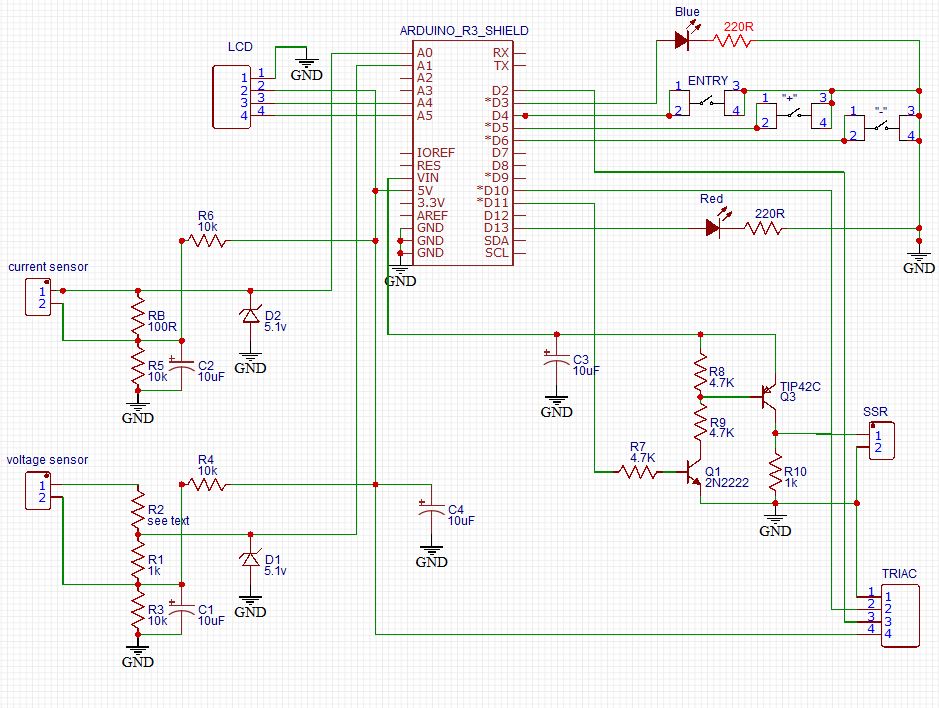
1* shield : see manual documentation for wiring implementation
1* triac dimming module with zero-cross detection
3* push-buttons
1* SSR + 1* transistor NPN, 1* transistor PNP, few resistors, capacitors...
Pinup :
- pin A0 (analog 0) => AC current sensor
- pin A1 (analog 1) => AC voltage sensor
- pin A4 (analog 4) => SDA output for LCD
- pin A5 (analog 5) => SCL output for LCD
- pin 2 (numeric 2) => zero-cross detection
- pin 3 (numeric 3) => output to a LED which indicate pwm
- pin 4 (numeric 4) => input from push-button "entry"
- pin 5 (numeric 5) => input from push-button "+"
- pin 6 (numeric 6) => input from push-button "-"
- pin 10 (numeric 10) => pwm output that drives the Triac
- pin 11 (numeric 11) => output to load shedding
- pin 13 (numeric 13) => overflow LED alarm
Versions chronology:
version 0.5 - 3 may 2018 - first test with a Triac module
version 0.8 - 5 july 2018 - first working version, problem with current measure accuracy
version 1 - 6 july 2018 - tests with EmonLib.h
version 1.8 - 24 sept 2018 - ajustable step for pwm
version 1.9 - 12 oct 2018 - load shedding function added
version 2.0 - 4 nov. 2018 - watchdog and EEPROM added
version 2.4 - 12 jan 2019 - LCD 1602 display added
version 3.2 - 17 jan 2019 - no more EmonLib.h
version 3.4 - 27 avr 2019 - stability improvment, load shedding with delestON and delestOFF
version 3.5 - 9 july 2019 - bug correction if no zero-cress detected which make rebooting infinitely
version 3.6 - 17 july 2019 - menues for parameters setup
*/
#include <EEPROM.h>
#include <avr/wdt.h> // documentation: https://tushev.org/articles/arduino/5/arduino-and-watchdog-timer
#include <TimerOne.h> // library to install: http://www.arduino.cc/playground/Code/Timer1
#include <LiquidCrystal_I2C.h> // library to install: https://app.box.com/s/czde88f5b9vpulhf8z56
// calibration variables:
bool CALIBRATION = false; // if true = adjustment of Vcalibration and Icalibration
bool VERBOSE = false; // if true = console display BUT VERY SLOW
// Calibration of measures which depend of the hardware. Must be done once at the beginning :
// first: ajust Vcalibration for reading 230V on the console
// after: Icalibration by comparing with a multimeter
// optional: phasecalibration can be adjust with the help of a powermeter
float Vcalibration = 0.97; // to obtain 230V
float Icalibration = 40.6; // to adjust the current reading to reality
float phasecalibration = 1.7; // to correct the phase shift due to hardware
byte totalCount = 20; // number of half-period studied measuring cycle
// power thresholds in Watts
int limitP = 1; // hysteresis of tolerance for the Triac action: if 1 => sensibility is +1W/-1W
int delestON = 1; // threshold to start the load shedding
int delestOFF = 350; // value to stop the load shedding
bool etat_delest_repos = HIGH; // inactive state of the load shedding: HIGH for switched on
// Reactance level to calculate dimstep :
// dimstep evoluates by the factor 'power to dissiate'/reactancelevel
// it is a compromise between reaction speed and instability:
// too small = instability risk, too high = slower
// help how to calculate: reactancelevel ~ (dissipation power of the load in Watts)/40
unsigned int reactancelevel = 9;
// Arduino inputs and outputs
const byte pushEntryPin = 4; // push button 'entry'
const byte pushPlusPin = 5; // push button '+'
const byte pushMinusPin = 6; // push button '-'
const byte triacPin = 10; // pwm output to Triac gate
const byte delestPin = 11; // output for load shedding
const byte triacLedPin = 3; // LED display Triac activity
const byte limitLedPin = 13; // LED for power overflow
const byte voltageSensorPin = 1; // input from voltage sensor
const byte currentSensorPin = 0; // input from current sensor
const byte zeroCrossPin = 2; // input from zero-cross detection
// variables for interruptions (zero-crossing) :
byte dimmax = 128; // max value of dim that shuttoff the Triac
byte dim = dimmax; // Dimming level (0-128) 0 = on, 128 = 0ff
char periodStep = 75; // value of the timer (65 for 60Hz, 78 for 50Hz, in s)
// according the formula (500000/AC_freq)/NumSteps = periodStep
// 78*128=10ms=1/2 period 50Hz but in fact 75 works better
volatile int i = 0; // Variable to use as a counter
volatile bool zero_cross = false; // zero-cross detected for driving the Triac
volatile bool zero_cross_flag = false; // zero-cross detected for power calcultion
// variables for electrical mesasures
int readV, memo_readV, readI; // voltage and current in bits (0 1023 bits)
float rPower, V, I, sqV, sumV = 0, sqI, sumI = 0, instP, sumP = 0;
byte zero_crossCount = 0; // halp-period counter
// other variables
int dimstep; // value of the increment of dim
unsigned long loadsheddingcounter; // time counter of load shedding duration
unsigned int memo_temps = 0;
bool delestage = false; // load shedding state
bool unefois = false; // for one time only flag
bool etat_delest_actif = !etat_delest_repos; // active loads shedding state
byte ret_push_button = 0;
byte windows = 0;
byte count_before_timeout = 0;
byte refresh_tempo = 2;
byte timeout = 20;
// LCD declaration with I2C :
// documentation : http://arduino-info.wikispaces.com/LCD-Blue-I2C
// Set the pins on the I2C chip used for LCD connections:
// addr, en,rw,rs,d4,d5,d6,d7,bl,blpol
LiquidCrystal_I2C lcd(0x27, 2, 1, 0, 4, 5, 6, 7, 3, POSITIVE);
// => pinup for I2C with l'Arduino Uno R3 : SDA = A4, SCL = A5
//
// SETUP
//_____________________________________________________________________________________________
void setup() { // Begin setup
pinMode(pushEntryPin, INPUT_PULLUP); // set the push-buttons as entries pullup to +5V
pinMode(pushPlusPin, INPUT_PULLUP);
pinMode(pushMinusPin, INPUT_PULLUP);
pinMode(triacPin, OUTPUT); // Set the Triac pin as output
pinMode(delestPin, OUTPUT);
pinMode(triacLedPin, OUTPUT); // Set the LED pin as output
pinMode(limitLedPin, OUTPUT);
attachInterrupt(digitalPinToInterrupt(zeroCrossPin), zero_cross_detect, RISING);
// each zeroCrossPin rising generates an interruption : the function 'zero_cross_detect()' is called
// documentation : https://www.arduino.cc/reference/en/language/functions/external-interrupts/attachinterrupt/
Timer1.initialize(periodStep); // TimerOne from library initialisation
Timer1.attachInterrupt(dim_check, periodStep);
// for every periodStep time spent, dim_check is called
// EEPROM functions are used to calculate how many time the device has rebooted
// EEPROM stored values are of type char.
// default values in case of first use are set to 255
unsigned char reboot_high = EEPROM.read(0); // to get the high value of the number
unsigned char reboot_low = EEPROM.read(1); // to get the low value of the number
unsigned int reboot = (reboot_high << 8) + reboot_low;
reboot++;
EEPROM.update(0, highByte(reboot));
EEPROM.update(1, lowByte(reboot));
// EEPROM functions are used to store parameters
if(EEPROM.read(2) < 200) limitP = EEPROM.read(2); else EEPROM.write(2, limitP);
if(EEPROM.read(3) < 50) delestON = EEPROM.read(3); else EEPROM.write(3, delestON);
unsigned char delestOFF_high = EEPROM.read(4);
unsigned char delestOFF_low = EEPROM.read(5);
int delestOFF_full = (delestOFF_high << 8) + delestOFF_low;
if( delestOFF_full < 10001 ) delestOFF = delestOFF_full;
else {
EEPROM.write(4, highByte(delestOFF));
EEPROM.write(5, lowByte(delestOFF));
}
if(EEPROM.read(6) < 2) etat_delest_repos = EEPROM.read(6); else EEPROM.write(6, etat_delest_repos);
if(EEPROM.read(7) < 255) reactancelevel = EEPROM.read(7); else EEPROM.write(7, reactancelevel);
if(EEPROM.read(8) < 31) phasecalibration = (EEPROM.read(8))/10.0; else EEPROM.write(8, (phasecalibration*10));
// LCD initialisation
lcd.begin(16,2); // initialize the lcd for 16 chars 2 lines
lcd.clear();
lcd.setCursor(0, 0);
lcd.print("POWER ROUTER");
lcd.setCursor(0, 1);
lcd.print("is starting !");
// console initialisation
Serial.begin(250000);
Serial.println ();
Serial.print("PLEASE NOTE : ");
Serial.print(reboot);
Serial.println(" total number of reboots");
Serial.println();
Serial.println("Ready to start ...");
Serial.println ();
delay(500);
if( VERBOSE == true ) Serial.print(" Pu (W) || dimstep | dim || load shedding");
else Serial.println("It is working now !");
Serial.println();
digitalWrite(delestPin, etat_delest_repos); // state output to the default load shedding state
wdt_enable(WDTO_500MS); // watchdog = reset if no activity longer than 500ms
} // End setup
//
// ZERO CROSS DETECT : zero-cross interrupt
//____________________________________________________________________________________________
void zero_cross_detect() { // this function is called at each zero-cross interrupt
zero_cross_flag = true; // flag for the real power calculation
zero_cross = true; // flag to drive the Triac
}
//
// DIM CHECK : drive the Triac
//____________________________________________________________________________________________
void dim_check() { // Function will fire the triac at the proper time
if(zero_cross == true && dim < dimmax) // First check to make sure the zero-cross has
{ // happened else do nothing
if(i>dim) { // i is a counter that defines the fire delay. higher is dim longer i will count
digitalWrite(triacPin, HIGH); // and later the triac will fire
delayMicroseconds(50); // Pause briefly to ensure the triac turned on
digitalWrite(triacPin, LOW); // Turn off the Triac gate, but the triac stays switch on until OV
i = 0; // Reset the counter for the next cycle
zero_cross = false;
}
else i++; // If the dimming value has not been reached, increase it
} // End zero_cross check
} // End dim_check function
//
// LOOP
//____________________________________________________________________________________________
void loop() { // Main Loop
// 1st part: calculation of the real electric power rPower
//____________________________________________________________________________________________
//
unsigned int numberOfSamples = 0;
sumV = 0;
sumI = 0;
sumP = 0;
unsigned int temps_actuel = millis()/1000; // get the time spent in seconds
// increment zero_crossCount at each zero-cross until totalCount, then rPower value is calculated
if( zero_crossCount >= totalCount ) zero_crossCount = 0;
// as most as possible number of measures between the totalCount number of half-periods
// themself defined by zero-cross flag
while( zero_crossCount < totalCount ) {
if( zero_cross_flag == true ) { // increment of half-period count for each zero-cross
zero_cross_flag = false;
zero_crossCount++;
}
numberOfSamples++; // number of measures
memo_readV = readV; // memorize the past value
readV = analogRead(voltageSensorPin); // voltage measure in bits - 0V = bit 512
delayMicroseconds(50);
if( readV == memo_readV && readV > 509 && readV < 515 ) { // test if no grid
lcd.setCursor(0, 0);
lcd.print("ABSENCE DE ");
lcd.setCursor(0, 1);
lcd.print("TENSION SECTEUR ");
delay(200);
goto nogrid; // exit to the end of program
}
readI = analogRead(currentSensorPin); // current measure in bits - 0A = bit 512
delayMicroseconds(50);
// calculation of the effective values of voltage and current
if( CALIBRATION == true ) { // for calibration only
sqV= (readV -512.0) * (readV -512.0); // -512 as offset to get 0V = bit 0
sumV += sqV;
sqI = (readI -512.0) * (readI -512.0);
sumI += sqI;
} // end test upon CALIBRATION
// instant power calculation
instP = ((memo_readV -512.0) + phasecalibration * ((readV -512.0) - (memo_readV -512))) * (readI -512.0);
sumP +=instP;
} // End of while upon zero_crossCount
// memorization of the values
if( numberOfSamples > 0 ) {
if( CALIBRATION == true ) {
V = Vcalibration * sqrt(sumV / numberOfSamples);
I = Icalibration * sqrt(sumI / numberOfSamples);
}
rPower = ((Vcalibration * Icalibration * sumP )/ numberOfSamples) / 1000.0;
}
// 2nd part: dim and dimstep calculation to drive the Triac, and load shedding management
//____________________________________________________________________________________________
//
// dimstep calculation: higher is the power to take in charge, higher will be dimstep
if( rPower > 0 ) { dimstep = rPower/10/reactancelevel + 1; }
else { dimstep = 1 - rPower/10/reactancelevel; }
if( rPower > limitP ) { // injection increases, the delay to fire the Triac decreases
if( dim > dimstep ) dim -= dimstep; else dim = 0;
}
else if( rPower < -limitP ) { // injection decreases, the delay to fire the Triac decreases
if( dim + dimstep < dimmax ) dim += dimstep; else dim = dimmax;
}
if( dim < 1 ) digitalWrite(limitLedPin, HIGH); // overload LED
else { digitalWrite(limitLedPin, LOW); }
analogWrite(triacLedPin, dimmax-dim); // Write the value to the LED for testing
// load shedding management
if( rPower > -delestON) { delestage = true; } // threshold activation value for load shedding
if( delestage == true ) {
if( unefois == false ) {
digitalWrite(delestPin, etat_delest_actif); // load shedding driver update
loadsheddingcounter = temps_actuel; // for load shedding spent time
unefois = true;
}
if( rPower < -delestOFF ) { // threshold inactive value for load shedding
digitalWrite(delestPin, etat_delest_repos); // load shedding driver update
unefois = false;
delestage = false;
}
} // end of test upon delestON
// LCD and menues management
//_______________________________________________
//
// display update and push-button request every 2 seconds
if( temps_actuel >= memo_temps + refresh_tempo ) {
memo_temps = temps_actuel;
ret_push_button = push_button(); // reading push-button status here only
lcd.clear();
lcd.setCursor(0, 0);
if( ret_push_button == 1 ) next_windows(); // if 'entry' pushed increase of window
if( windows == 0 ) {
lcd.print("P= ");
lcd.print(String(-rPower,0));
lcd.print("w");
lcd.setCursor(10, 0);
lcd.print("T= ");
lcd.print( map(dim, 0, dimmax, 99, 0) );
lcd.print("%");
lcd.setCursor(0, 1);
lcd.print("DELESTAGE "); // load shedding in French
if( delestage == true ) {
lcd.print(temps_actuel - loadsheddingcounter);
lcd.print("s ");
}
else { lcd.print("ARRETE"); } // stoped in French
}
else { // end of window 0, start of parameters review
count_before_timeout++;
if( count_before_timeout > timeout ) { // timeout to return to usual display if no job done
count_before_timeout = 0;
windows = 0;
}
if( windows == 1 ) {
if(ret_push_button == 2) limitP++; // if "+" pushed
if(ret_push_button == 3) limitP--; // if "-" pushed
limitP = constrain(limitP, 1, 200);
lcd.print("SEUIL DETECTION");
lcd.setCursor(0, 1);
lcd.print("seuil = ");
lcd.setCursor(8, 1);
lcd.print(limitP);
lcd.print("W");
} // end of windows 1
if( windows == 2 ) {
if(ret_push_button == 2) delestON++; // if "+" pushed
if(ret_push_button == 3) delestON--; // if "-" pushed
delestON = constrain(delestON, 1, 50);
lcd.print("DELESTAGE ACTIF");
lcd.setCursor(0, 1);
lcd.print("seuil = ");
lcd.setCursor(8, 1);
lcd.print(delestON);
lcd.print("W");
} // end of windows 2
if( windows == 3 ) {
if(ret_push_button == 2) delestOFF+= 50; // if "+" pushed
if(ret_push_button == 3) delestOFF-= 50; // if "-" pushed
delestOFF = constrain(delestOFF, 50, 10000);
lcd.print("DELESTAGE ARRET");
lcd.setCursor(0, 1);
lcd.print("seuil = ");
lcd.setCursor(8, 1);
lcd.print(delestOFF);
lcd.print("W");
} // end of windows 3
if( windows == 4 ) {
if( ret_push_button > 1 ) etat_delest_repos =! etat_delest_repos;
etat_delest_actif =! etat_delest_repos;
lcd.print("DELESTAGE :");
lcd.setCursor(0, 1);
if( etat_delest_repos == HIGH ) lcd.print("DEMARRE au repos");
else lcd.print("ARRETE au repos");
} // end of windows 4
if( windows == 5 ) {
if(ret_push_button == 2) reactancelevel++; // if "+" pushed
if(ret_push_button == 3) reactancelevel--; // if "-" pushed
reactancelevel = constrain(reactancelevel, 1, 254);
lcd.print("COEF DE REACTION");
lcd.setCursor(0, 1);
lcd.print("taux = ");
lcd.setCursor(7, 1);
lcd.print(reactancelevel);
} // end of windows 5
if( windows == 6 ) {
byte phasecalibrationDEC = phasecalibration*10;
if(ret_push_button == 2) phasecalibrationDEC++; // if "+" pushed
if(ret_push_button == 3) phasecalibrationDEC--; // if "-" pushed
phasecalibrationDEC = constrain(phasecalibrationDEC, 1, 30);
phasecalibration = phasecalibrationDEC/10.0;
lcd.print("CALIBRATION Pu");
lcd.setCursor(0, 1);
lcd.print("valeur = ");
lcd.setCursor(9, 1);
lcd.print(phasecalibration);
} // end of windows 6
// EEPROM updated if needed
EEPROM.update(2, limitP);
EEPROM.update(3, delestON);
EEPROM.update(4, highByte(delestOFF));
EEPROM.update(5, lowByte(delestOFF));
EEPROM.update(6, etat_delest_repos);
EEPROM.update(7, reactancelevel);
EEPROM.update(8, (phasecalibration*10));
} // end of paramerter review
} // end of display management
// console display
if( CALIBRATION == true ) {
Serial.print(V);
Serial.print(" | ");
Serial.print(I/1000);
Serial.print(" | ");
Serial.print(rPower);
Serial.println();
}
if( VERBOSE == true ) {
Serial.print(rPower);
Serial.print(" || ");
Serial.print(dimstep);
Serial.print(" | ");
Serial.print(dim);
Serial.print(" || ");
Serial.print(" load shedding : ");
Serial.print(delestage);
Serial.print(" seconds : ");
Serial.println(temps_actuel - loadsheddingcounter);
}
else delay(1); // required for stability
nogrid:
wdt_reset(); // watchdog reset
} // end of main Loop
//
// NEXT_WINDOWS : next windows procedure
//____________________________________________________________________________________________
void next_windows() {
windows = (windows+1) % 7; // next windows modulo 6
ret_push_button = 0; // reset the buttun state
lcd.clear();
lcd.setCursor(0, 0);
} // end of next_windows function
//
// PUSH_BUTTON : return value depending of the state of the 3 push-buttons
//____________________________________________________________________________________________
byte push_button() {
if( digitalRead(pushEntryPin) == 0 ) {
count_before_timeout = 0; // reset the timeout counter
return 1;
}
if( digitalRead(pushPlusPin) == 0 ) {
count_before_timeout = 0; // reset the timeout counter
refresh_tempo = 1; // temporary lower display update duration
return 2;
}
if( digitalRead(pushMinusPin) == 0 ) {
count_before_timeout = 0; // reset the timeout counter
refresh_tempo = 1; // temporary lower display update duration
return 3;
}
refresh_tempo = 2; // go back to initial value
return 0;
} // end of push_button function
/*

A Power Router is a device that detects any homemade electrical energy in exceed. If so
several actions can be taken :
- with the Triac function: gradually switch on a resistive load that will take all the
  exceed energy. This load must be resistive (edison light, water heat, etc...) due to
  the power factor which must stay near 1.
- with the SSR function: prevent against any exceed by performing a load shedding : just
  before injection in the public power grid, either a load can be add to increase
  consumtion, or a power generator (solar panel, wind turbine) can be stopped.

The operation is performed by:
- a shift detection between the grid current and the voltage which detect a power consumption
  or a power injection.
- in case of injection it initiates the gradual absorption by a resistive load of any exceed power
- the current measure allows the absorption adjustment
- a load shedding becomes active when the system is very near injection and automatically
  stops as soon as a level of consumption is raised.

This device is actually in operation in two homes with a power load of 350W and 1000W.

Thanks to Ryan McLaughlin for its description of the triac dimming:
https://web.archive.org/web/20091212193047/http://www.arduino.cc:80/cgi-bin/yabb2/YaBB.pl?num=1230333861/15

_________________________________________________________________
|                                                               |
|       author : Philippe de Craene <dcphilippe@yahoo.fr        |
|       Free of use - Any feedback is welcome                   |
                                                                |
_________________________________________________________________

Materials :
 1* Arduino Uno R3 - IDE version 1.8.7
 1* AC current sensor 20A/25mA
 1* AC-AC 230V-2.5V transformer
 1* LCD 1602 with I2C extension
 1* shield : see manual documentation for wiring implementation
 1* triac dimming module with zero-cross detection
 3* push-buttons
 1* SSR + 1* transistor NPN, 1* transistor PNP, few resistors, capacitors...

Pinup :
 - pin A0 (analog 0)   => AC current sensor
 - pin A1 (analog 1)   => AC voltage sensor
 - pin A4 (analog 4)   => SDA output for LCD
 - pin A5 (analog 5)   => SCL output for LCD
 - pin  2 (numeric 2)  => zero-cross detection
 - pin  3 (numeric 3)  => output to a LED which indicate pwm
 - pin  4 (numeric 4)  => input from push-button "entry"
 - pin  5 (numeric 5)  => input from push-button "+"
 - pin  6 (numeric 6)  => input from push-button "-"
 - pin 10 (numeric 10) => pwm output that drives the Triac
 - pin 11 (numeric 11) => output to load shedding
 - pin 13 (numeric 13) => overflow LED alarm

Versions chronology:
version 0.5 - 3 may  2018   - first test with a Triac module
version 0.8 - 5 july 2018   - first working version, problem with current measure accuracy
version 1   - 6 july 2018   - tests with EmonLib.h
version 1.8 - 24 sept 2018  - ajustable step for pwm
version 1.9 - 12 oct 2018   - load shedding function added
version 2.0 - 4 nov. 2018   - watchdog and EEPROM added
version 2.4 - 12 jan 2019   - LCD 1602 display added
version 3.2 - 17 jan 2019   - no more EmonLib.h
version 3.4 - 27 avr 2019   - stability improvment, load shedding with delestON and delestOFF
version 3.5 -  9 july 2019  - bug correction if no zero-cress detected which make rebooting infinitely
version 3.6 - 17 july 2019  - menues for parameters setup
version 3.7 - 28 oct 2019   - replacement of the LiquidCrystal_I2C library

*/

#include <EEPROM.h>
#include <avr/wdt.h>    // documentation: https://tushev.org/articles/arduino/5/arduino-and-watchdog-timer
#include <TimerOne.h>   // library to install: http://www.arduino.cc/playground/Code/Timer1
#include <LiquidCrystal_I2C.h>    // https://github.com/fdebrabander/Arduino-LiquidCrystal-I2C-library

// calibration variables:

bool CALIBRATION = false;   // if true = adjustment of Vcalibration and Icalibration
bool VERBOSE =     false;   // if true = console display BUT VERY SLOW

// Calibration of measures which depend of the hardware. Must be done once at the beginning :
// first: ajust Vcalibration for reading 230V on the console
// after: Icalibration by comparing with a multimeter
// optional: phasecalibration can be adjust with the help of a powermeter

float Vcalibration     = 0.97;   // to obtain 230V
float Icalibration     = 40.6;   // to adjust the current reading to reality
float phasecalibration = 1.7;    // to correct the phase shift due to hardware
byte totalCount        = 20;     // number of half-period studied measuring cycle

// power thresholds in Watts

int limitP    = 1;    // hysteresis of tolerance for the Triac action: if 1 => sensibility is +1W/-1W
int delestON  = 1;               // threshold to start the load shedding
int delestOFF = 350;             // value to stop the load shedding
bool etat_delest_repos  = HIGH;  // inactive state of the load shedding: HIGH for switched on

// Reactance level to calculate dimstep :
// dimstep evoluates by the factor 'power to dissiate'/reactancelevel
// it is a compromise between reaction speed and instability:
// too small = instability risk, too high = slower
// help how to calculate: reactancelevel ~ (dissipation power of the load in Watts)/40

unsigned int reactancelevel  = 9;

// Arduino inputs and outputs

const byte pushEntryPin     =  4;    // push button 'entry'
const byte pushPlusPin      =  5;    // push button '+'
const byte pushMinusPin     =  6;    // push button '-'
const byte triacPin         = 10;    // pwm output to Triac gate
const byte delestPin        = 11;    // output for load shedding
const byte triacLedPin      =  3;    // LED display Triac activity
const byte limitLedPin      = 13;    // LED for power overflow
const byte voltageSensorPin =  1;    // input from voltage sensor
const byte currentSensorPin =  0;    // input from current sensor
const byte zeroCrossPin     =  2;    // input from zero-cross detection

// variables for interruptions (zero-crossing) :

byte dimmax = 128;              // max value of dim that shuttoff the Triac
byte dim = dimmax;              // Dimming level (0-128)  0 = on, 128 = 0ff
char periodStep = 75;           // value of the timer (65 for 60Hz, 78 for 50Hz, in s)
                                // according the formula (500000/AC_freq)/NumSteps = periodStep
                                // 78*128=10ms=1/2 period 50Hz but in fact 75 works better
volatile int i = 0;             // Variable to use as a counter
volatile bool zero_cross = false;       // zero-cross detected for driving the Triac
volatile bool zero_cross_flag = false;  // zero-cross detected for power calcultion

// variables for electrical mesasures

int readV, memo_readV, readI;           // voltage and current in bits (0  1023 bits)
float rPower, V, I, sqV, sumV = 0, sqI, sumI = 0, instP, sumP = 0;
byte zero_crossCount = 0;               // halp-period counter

// other variables

int dimstep;                            // value of the increment of dim
unsigned long loadsheddingcounter;      // time counter of load shedding duration
unsigned int memo_temps = 0;
bool delestage = false;                 // load shedding state
bool unefois = false;                   // for one time only flag
bool etat_delest_actif = !etat_delest_repos;  // active loads shedding state
byte ret_push_button = 0;
byte windows = 0;
byte count_before_timeout = 0;
byte refresh_tempo = 2;
byte timeout = 20;

// LCD declaration with I2C :

// documentation : http://arduino-info.wikispaces.com/LCD-Blue-I2C
// Set the pins on the I2C chip used for LCD connections:
//                   addr, en,rw,rs,d4,d5,d6,d7,bl,blpol
LiquidCrystal_I2C lcd(0x27, 2, 1, 0, 4, 5, 6, 7, 3, POSITIVE);
// => pinup for I2C with l'Arduino Uno R3 : SDA = A4, SCL = A5


//
// SETUP
//_____________________________________________________________________________________________

void setup() {                          // Begin setup
  pinMode(pushEntryPin, INPUT_PULLUP);  // set the push-buttons as entries pullup to +5V
  pinMode(pushPlusPin, INPUT_PULLUP);
  pinMode(pushMinusPin, INPUT_PULLUP);
  pinMode(triacPin, OUTPUT);            // Set the Triac pin as output
  pinMode(delestPin, OUTPUT);
  pinMode(triacLedPin, OUTPUT);         // Set the LED pin as output
  pinMode(limitLedPin, OUTPUT);

  attachInterrupt(digitalPinToInterrupt(zeroCrossPin), zero_cross_detect, RISING);
// each zeroCrossPin rising generates an interruption : the function 'zero_cross_detect()' is called
// documentation : https://www.arduino.cc/reference/en/language/functions/external-interrupts/attachinterrupt/

  Timer1.initialize(periodStep);         // TimerOne from library initialisation
  Timer1.attachInterrupt(dim_check, periodStep);
// for every periodStep time spent, dim_check is called

// EEPROM functions are used to calculate how many time the device has rebooted
// EEPROM stored values are of type char.
// default values in case of first use are set to 255
  unsigned char reboot_high = EEPROM.read(0);  // to get the high value of the number
  unsigned char reboot_low  = EEPROM.read(1);  // to get the low value of the number
  unsigned int reboot = (reboot_high << 8) + reboot_low;
  reboot++;
  EEPROM.update(0, highByte(reboot));
  EEPROM.update(1, lowByte(reboot));

// EEPROM functions are used to store parameters
  if(EEPROM.read(2) < 200)  limitP = EEPROM.read(2); else EEPROM.write(2, limitP);
  if(EEPROM.read(3) < 50) delestON = EEPROM.read(3); else EEPROM.write(3, delestON);
  unsigned char delestOFF_high = EEPROM.read(4);
  unsigned char delestOFF_low  = EEPROM.read(5);
  int delestOFF_full = (delestOFF_high << 8) + delestOFF_low;
  if( delestOFF_full < 10001 ) delestOFF = delestOFF_full;
  else {
    EEPROM.write(4, highByte(delestOFF));
    EEPROM.write(5, lowByte(delestOFF));
  }
  if(EEPROM.read(6) < 2) etat_delest_repos = EEPROM.read(6); else EEPROM.write(6, etat_delest_repos);
  if(EEPROM.read(7) < 255)  reactancelevel = EEPROM.read(7); else EEPROM.write(7, reactancelevel);
  if(EEPROM.read(8) < 31) phasecalibration = (EEPROM.read(8))/10.0; else EEPROM.write(8, (phasecalibration*10));

// LCD initialisation
  lcd.begin();                // initialize the lcd for 16 chars 2 lines
  lcd.clear();
  lcd.setCursor(0, 0);
  lcd.print("POWER ROUTER");
  lcd.setCursor(0, 1);
  lcd.print("is starting !");

// console initialisation
  Serial.begin(250000);
  Serial.println ();
  Serial.print("PLEASE NOTE : ");
  Serial.print(reboot);
  Serial.println(" total number of reboots");
  Serial.println();
  Serial.println("Ready to start ...");
  Serial.println ();
  delay(500);
  if( VERBOSE == true ) Serial.print("  Pu (W) || dimstep |  dim ||  load shedding");
  else Serial.println("It is working now !");
  Serial.println();

  digitalWrite(delestPin, etat_delest_repos);    // state output to the default load shedding state
  wdt_enable(WDTO_500MS);                        // watchdog = reset if no activity longer than 500ms

}                // End setup


//
// ZERO CROSS DETECT : zero-cross interrupt
//____________________________________________________________________________________________

void zero_cross_detect() {   // this function is called at each zero-cross interrupt
  zero_cross_flag = true;    // flag for the real power calculation
  zero_cross = true;         // flag to drive the Triac
}

//
// DIM CHECK : drive the Triac
//____________________________________________________________________________________________

void dim_check() {                         // Function will fire the triac at the proper time
  if(zero_cross == true && dim < dimmax)   // First check to make sure the zero-cross has
  {                                        // happened else do nothing
    if(i>dim) {            // i is a counter that defines the fire delay. higher is dim longer i will count
      digitalWrite(triacPin, HIGH);        // and later the triac will fire
      delayMicroseconds(50);               // Pause briefly to ensure the triac turned on
      digitalWrite(triacPin, LOW);         // Turn off the Triac gate, but the triac stays switch on until OV
      i = 0;                               // Reset the counter for the next cycle
      zero_cross = false;
    }
    else i++;    // If the dimming value has not been reached, increase it
  }              // End zero_cross check
}                // End dim_check function


//
// LOOP
//____________________________________________________________________________________________

void loop() {                  // Main Loop

// 1st part: calculation of the real electric power rPower
//____________________________________________________________________________________________
//

  unsigned int numberOfSamples = 0;
  sumV = 0;
  sumI = 0;
  sumP = 0;
  unsigned int temps_actuel = millis()/1000;      // get the time spent in seconds

// increment zero_crossCount at each zero-cross until totalCount, then rPower value is calculated

  if( zero_crossCount >= totalCount ) zero_crossCount = 0;

// as most as possible number of measures between the totalCount number of half-periods
// themself defined by zero-cross flag
  while( zero_crossCount < totalCount ) {
    if( zero_cross_flag == true ) {         // increment of half-period count for each zero-cross
      zero_cross_flag = false;
      zero_crossCount++;
    }
    numberOfSamples++;                      // number of measures
    memo_readV = readV;                     // memorize the past value
    readV = analogRead(voltageSensorPin);   // voltage measure in bits - 0V = bit 512
    delayMicroseconds(50);
    if( readV == memo_readV && readV > 509 && readV < 515 ) {   // test if no grid
      lcd.setCursor(0, 0);
      lcd.print("ABSENCE DE      ");
      lcd.setCursor(0, 1);
      lcd.print("TENSION SECTEUR ");
      delay(200);
      goto nogrid;                          // exit to the end of program
    }
    readI = analogRead(currentSensorPin);   // current measure in bits - 0A = bit 512
    delayMicroseconds(50);

// calculation of the effective values of voltage and current
    if( CALIBRATION == true ) {                   // for calibration only
      sqV= (readV -512.0) * (readV -512.0);       // -512 as offset to get 0V = bit 0
      sumV += sqV;
      sqI = (readI -512.0) * (readI -512.0);
      sumI += sqI;
    }    //   end test upon CALIBRATION

// instant power calculation
    instP = ((memo_readV -512.0) + phasecalibration * ((readV -512.0) - (memo_readV -512))) * (readI -512.0);
    sumP +=instP;
 }      // End of while upon zero_crossCount

// memorization of the values
  if( numberOfSamples > 0 ) {
    if( CALIBRATION == true ) {
      V = Vcalibration * sqrt(sumV / numberOfSamples);
      I = Icalibration * sqrt(sumI / numberOfSamples);
    }
    rPower = ((Vcalibration * Icalibration * sumP )/ numberOfSamples) / 1000.0;
  }

// 2nd part: dim and dimstep calculation to drive the Triac, and load shedding management
//____________________________________________________________________________________________
//

// dimstep calculation: higher is the power to take in charge, higher will be dimstep
  if( rPower > 0 ) { dimstep = rPower/10/reactancelevel + 1; }
  else { dimstep = 1 - rPower/10/reactancelevel; }

  if( rPower > limitP ) {             // injection increases, the delay to fire the Triac decreases
    if( dim > dimstep )  dim -= dimstep; else  dim = 0;
  }
  else if( rPower < -limitP ) {       // injection decreases, the delay to fire the Triac decreases
    if( dim + dimstep < dimmax ) dim += dimstep;  else  dim = dimmax;
  }

  if( dim < 1 ) digitalWrite(limitLedPin, HIGH);     // overload LED
  else { digitalWrite(limitLedPin, LOW); }
  analogWrite(triacLedPin, dimmax-dim);              // Write the value to the LED for testing

// load shedding management
  if( rPower > -delestON) { delestage = true; }      // threshold activation value for load shedding

  if( delestage == true ) {
    if( unefois == false ) {
      digitalWrite(delestPin, etat_delest_actif);     // load shedding driver update
      loadsheddingcounter = temps_actuel;             // for load shedding spent time
      unefois = true;
    }
    if( rPower < -delestOFF ) {                       // threshold inactive value for load shedding
      digitalWrite(delestPin, etat_delest_repos);     // load shedding driver update
      unefois = false;
      delestage = false;
    }
  }           // end of test upon delestON

// LCD and menues management
//_______________________________________________
//
// display update and push-button request every 2 seconds
  if( temps_actuel >= memo_temps + refresh_tempo ) {
    memo_temps = temps_actuel;
    ret_push_button = push_button();       // reading push-button status here only
    lcd.clear();
    lcd.setCursor(0, 0);
    if( ret_push_button == 1 ) next_windows();   // if 'entry' pushed increase of window
    if( windows == 0 ) {
      lcd.print("P= ");
      lcd.print(String(-rPower,0));
      lcd.print("w");
      lcd.setCursor(10, 0);
      lcd.print("T= ");
      lcd.print( map(dim, 0, dimmax, 99, 0) );
      lcd.print("%");
      lcd.setCursor(0, 1);
      lcd.print("DELESTAGE ");             // load shedding in French
      if( delestage == true ) {
        lcd.print(temps_actuel - loadsheddingcounter);
        lcd.print("s    ");
      }
      else { lcd.print("ARRETE"); }        // stoped in French
    }
    else {                                 //  end of window 0, start of parameters review
      count_before_timeout++;
      if( count_before_timeout > timeout ) {   // timeout to return to usual display if no job done
        count_before_timeout = 0;
        windows = 0;
        lcd.noBacklight();
      }
      if( windows == 1 ) {
        if(ret_push_button == 2) limitP++;    // if "+" pushed
        if(ret_push_button == 3) limitP--;    // if "-" pushed
        limitP = constrain(limitP, 1, 200);
        lcd.print("SEUIL DETECTION");
        lcd.setCursor(0, 1);
        lcd.print("seuil = ");
        lcd.setCursor(8, 1);
        lcd.print(limitP);
        lcd.print("W");
      }  // end of windows 1
      if( windows == 2 ) {
        if(ret_push_button == 2) delestON++;    // if "+" pushed
        if(ret_push_button == 3) delestON--;    // if "-" pushed
        delestON = constrain(delestON, 1, 50);
        lcd.print("DELESTAGE ACTIF");
        lcd.setCursor(0, 1);
        lcd.print("seuil = ");
        lcd.setCursor(8, 1);
        lcd.print(delestON);
        lcd.print("W");
      }  // end of windows 2
      if( windows == 3 ) {
        if(ret_push_button == 2) delestOFF+= 50;    // if "+" pushed
        if(ret_push_button == 3) delestOFF-= 50;    // if "-" pushed
        delestOFF = constrain(delestOFF, 50, 10000);
        lcd.print("DELESTAGE ARRET");
        lcd.setCursor(0, 1);
        lcd.print("seuil = ");
        lcd.setCursor(8, 1);
        lcd.print(delestOFF);
        lcd.print("W");
      }  // end of windows 3
      if( windows == 4 ) {
        if( ret_push_button > 1 ) etat_delest_repos =! etat_delest_repos;
        etat_delest_actif =! etat_delest_repos;
        lcd.print("DELESTAGE :");
        lcd.setCursor(0, 1);
        if( etat_delest_repos == HIGH ) lcd.print("DEMARRE au repos");
        else lcd.print("ARRETE au repos");
      }   // end of windows 4
      if( windows == 5 ) {
        if(ret_push_button == 2) reactancelevel++;    // if "+" pushed
        if(ret_push_button == 3) reactancelevel--;    // if "-" pushed
        reactancelevel = constrain(reactancelevel, 1, 254);
        lcd.print("COEF DE REACTION");
        lcd.setCursor(0, 1);
        lcd.print("taux = ");
        lcd.setCursor(7, 1);
        lcd.print(reactancelevel);
      }  // end of windows 5
      if( windows == 6 ) {
        byte phasecalibrationDEC = phasecalibration*10;
        if(ret_push_button == 2) phasecalibrationDEC++;    // if "+" pushed
        if(ret_push_button == 3) phasecalibrationDEC--;    // if "-" pushed
        phasecalibrationDEC = constrain(phasecalibrationDEC, 1, 30);
        phasecalibration = phasecalibrationDEC/10.0;
        lcd.print("CALIBRATION Pu");
        lcd.setCursor(0, 1);
        lcd.print("valeur = ");
        lcd.setCursor(9, 1);
        lcd.print(phasecalibration);
      }  // end of windows 6

// EEPROM updated if needed
      EEPROM.update(2, limitP);
      EEPROM.update(3, delestON);
      EEPROM.update(4, highByte(delestOFF));
      EEPROM.update(5, lowByte(delestOFF));
      EEPROM.update(6, etat_delest_repos);
      EEPROM.update(7, reactancelevel);
	    EEPROM.update(8, (phasecalibration*10));

    }   // end of paramerter review
  }     // end of display management

// console display
  if( CALIBRATION == true ) {
	  Serial.print(V);
	  Serial.print("  |  ");
    Serial.print(I/1000);
    Serial.print("  |  ");
    Serial.print(rPower);
    Serial.println();
  }
  if( VERBOSE == true ) {
    Serial.print(rPower);
    Serial.print("  ||     ");
    Serial.print(dimstep);
    Serial.print("  |  ");
    Serial.print(dim);
    Serial.print(" ||  ");
    Serial.print(" load shedding : ");
    Serial.print(delestage);
    Serial.print(" seconds : ");
    Serial.println(temps_actuel - loadsheddingcounter);
  }
  else delay(1);               // required for stability
  nogrid:
  wdt_reset();                 // watchdog reset

}                              // end of main Loop

//
// NEXT_WINDOWS : next windows procedure
//____________________________________________________________________________________________

void next_windows() {

  windows = (windows+1) % 7;        // next windows modulo 6
  ret_push_button = 0;              // reset the buttun state
  lcd.clear();
  lcd.setCursor(0, 0);
}     // end of next_windows function

//
// PUSH_BUTTON : return value depending of the state of the 3 push-buttons
//____________________________________________________________________________________________

byte push_button() {

  if( digitalRead(pushEntryPin) == 0 ) {
    count_before_timeout = 0;         // reset the timeout counter
    lcd.backlight();                  // switch on display
    return 1;
  }
  if( digitalRead(pushPlusPin) == 0 ) {
    count_before_timeout = 0;         // reset the timeout counter
    lcd.backlight();                  // switch on display
    refresh_tempo = 1;                // temporary lower display update duration
    return 2;
  }
  if( digitalRead(pushMinusPin) == 0 ) {
    count_before_timeout = 0;         // reset the timeout counter
    lcd.backlight();                  // switch on display
    refresh_tempo = 1;                // temporary lower display update duration
    return 3;
  }
  refresh_tempo = 2;                  // go back to initial value
  return 0;
}     // end of push_button function


Comments