

Hardware components | ||||||
 |
| × | 1 | |||
 |
| × | 1 | |||
| × | 2 | ||||
 |
| × | 1 | |||
 |
| × | 1 | |||
Hand tools and fabrication machines | ||||||
 |
| |||||
 |
| |||||
 |
| |||||
 |
| |||||
WHEN WILDLIFE MEETS HEADLIGHTS
Across regions like Kerala, roads cut silently through forests, dividing habitats and creating invisible conflict zones. For animals, these roads are strange intrusions into their natural paths, their home. For humans, they’re part of the daily commute—until the unexpected appears in front of their headlights.
Every year, these sudden encounters lead to more than just wildlife deaths. Drivers swerve in panic, vehicles crash, passengers are injured, and even lives are lost. The impact isn’t only emotional or ecological. It’s physical, financial, and deeply human.
From startled deer to charging elephants, the risk is real and unpredictable. Yet the systems we rely on like the static signboards, remain passive. They cannot adapt to the moment or reflect actual danger on the road.
When wildlife meets headlights, it’s often too late. Fauna Flash changes that — turning ordinary roads into intelligent safety corridors that sense, identify, and alert before tragedy strikes.
PROBLEM STATEMENTRoads through forests create a unique safety challenge. Wildlife often crosses without warning, and drivers have no real-time indication of what lies ahead.
- Static signs give only general caution, not specific, current danger.
- Reaction time is short; at 60 km/h, a driver has just over 1.5 seconds to respond.
This results in vehicle collisions, human injuries, fatalities, and the loss of protected species. A reliable, real-time system to detect and warn of approaching animals is essential. One that works day and night, in all weather, and adapts instantly to changing conditions.
SOLUTION OVERVIEWFauna Flash is a real-time wildlife detection and alert network built for forest roads. Using strategically placed night vision AI cameras, the system monitors animal movement across multiple points in the forest. When wildlife is detected near the road, roadside signposts instantly display dynamic warnings — tailored to the specific animal — giving drivers the time to slow down and react safely.
Operating seamlessly day and night, and resilient to rain, fog, and dust, the network creates a moving safety zone that adapts to the presence of wildlife. By turning static warnings into dynamic, data-driven alerts, Fauna Flash gives drivers the crucial seconds needed to prevent collisions, saving both human and animal lives while preserving the delicate balance of shared habits.
Testing & ApplicationTo validate the practicality of Fauna Flash, we conducted a pilot deployment along the Vadattpara road in the Malayatoor Forest Division, Edamalayar—a known hotspot for elephant movement. This stretch was selected after discussions with local forest officers, who confirmed frequent human–elephant encounters and identified danger-prone paths.
Before installing, we sought and received official permission from the forest department, ensuring ethical testing without disturbing wildlife. Only one alert post was deployed in this phase, focusing on observing driver behavior and system visibility.
During the site survey, one striking insight was the condition of existing static signboards. While these boards are meant to warn drivers, most were rusty and faded, making them nearly unreadable. Poorly maintained, with no updates or servicing despite years of installation.
Drivers admitted they often ignore these boards because they are always present but rarely relevant—failing to reflect actual wildlife activity. This reinforced the need for real-time, dynamic alerts that adapt to on-ground conditions.
After installing our solar-powered alert post, we observed driver responses in real time. Unlike static boards, the bright LED warnings immediately caught attention, prompting vehicles to slow down well before the danger zone.
We also conducted driver feedback sessions, showing them comparisons of static boards versus Fauna Flash alerts. The majority emphasized that dynamic, glowing signs felt urgent, trustworthy, and impossible to ignore, especially at night.
Following initial deployment, forest officers guided us on strategic placement of detection nodes. They pointed out specific elephant crossing corridors and routes of frequent conflict, such as farmland edges where elephants invade to raid crops.
Their insights shaped our plan for scaling beyond single posts—by creating a network of detection nodes feeding into alert posts at high-risk spots. This collaboration ensures Fauna Flash is rooted in ground realities of forest management.
To broaden validation, we engaged with local residents and commuters who travel these roads daily. Their accounts highlighted:
- Frequent elephant invasions destroying crops and property.
- Fear among travelers, especially at night, due to sudden encounters.
- Stories of near misses and attacks, where timely warnings could have saved both people and animals.
This community-driven feedback added depth to our testing, showing that Fauna Flash is not just a technical solution but a human-centered safety intervention.
SYSTEM OPERATIONThe system operates through three coordinated units—Detection node, a communication link, and an Alert post—to identify wildlife and instantly warn nearby traffic or people.
1)Detection Nodes
- A node consists of a Grove Vision AI V2 camera paired with a XIAO ESP32S3 microcontroller.
- The camera continuously monitors the surroundings, using a YOLOv8-based object detection model to recognize specific animals in real time.
- Once an animal is identified, the node transmits a corresponding alert code via its onboard RYLR998 LoRa module.
2) LoRa Communication Link
- The LoRa modules in both the detection node and the alert post ensure long-range, low-power communication, even in dense forest environments.
- Each animal type is assigned a unique code, enabling the receiving unit to quickly determine the appropriate visual alert.
3) Solar-Powered Alert Post (installed near roads or pathways)
- The post runs on solar power for independent operation.
- Inside the post’s control box, an Arduino Nano paired with another RYLR998 LoRa module receives the alert code from the detection node.
- Based on the code received, the Arduino instructs a P10 RGB LED matrix (driven via an HD-WF1 control card) to display a clear, symbolic warning such as an elephant icon for elephant sightings.
Now, let us dive deeper into the complete setup of the Detection Node, exploring each component, its role in the system, and the step-by-step process of integrating them into the system.
Detection Node – Complete Setup- Groove vision AI V2
- XIAO ESP32 S3(stacked)
- XIAO ESP32 S3
- RYAX RYLR998 (Lora module)
The Grove Vision AI V2 is an MCU-based vision AI module built on the Arm Cortex-M55 with Ethos-U55 NPU, designed for efficient edge AI processing. It supports TensorFlow and PyTorch models, works seamlessly with the Arduino IDE, and allows no-code ML model deployment via the SenseCraft AI platform.
In simple words, in our project we need this camera to capture video frames and runs object detection locally.
The product arrives in standard Seeed Studio packaging. Inside the box, you'll find:
- The Vision AI Module V2
- A connecting wire
- A sticker with a brief introduction to the module
Key features
- Night vision capability with IR LEDs
- Supports AI inference on-device (K210 chip)
- Compatible with custom YOLOv8-trained models
Hardware Overview
Connecting to a CSI interface camera
Once you have the Grove Vision AI V2 and camera ready to go, you can connect them via the CSI connection cable. While connecting, be careful with the direction of the row of pins. Don't plug them in backwards.
Boot / Reset / Flashed Driver
Entering BootLoader Mode
If you have applied an unconventional method that caused the Grove Vision AI device to malfunction at the software level, you might need to restore it by entering BootLoader mode. Below are the methods to put the device into BootLoader mode for recovery.
Method 1
Please disconnect the connection cable between the Grove Vision AI and your computer, then press and hold the Boot button on the device without releasing it. At this time, connect Grove Vision AI to your computer with a Type-C type data cable, and then release it again. At this point the device will enter BootLoader mode.
Method 2
With the Grove Vision AI connected to your computer, you can enter BootLoader mode by pressing the Boot button and then quickly pressing the Reset button.
Reset
If you're experiencing problems with device data suddenly not uploading or images getting stuck, you can try restarting your device using the Reset button.
Driver
If you find that the Grove Vision AI V2 is not recognised after connecting it to your computer. Then you may need to install the CH343 driver on your computer. Here are some links to download and install the CH343 driver.
- Windows Vendor VCP Driver One-Click Installer: CH343SER.EXE
- Windows Vendor VCP Driver: CH343SER.ZIP
- Windows CDC driver one-click installer: CH343CDC.EXE
- Windows CDC driver: CH343CDC.ZIP
- macOS Vendor VCP Driver: CH34xSER_MAC.ZIP
An equally important part of the detection node is the XIAO ESP32S3, a small but powerful microcontroller from Seeed Studio.It features built-in wireless connectivity, AI acceleration capabilities, and supports a wide range of expansion modules, making it ideal for edge AI projects.
our system, two of these modules works hand-in-hand with the Grove Vision AI V2 camera and RYLR998 LoRa module to process visual data and communicate results.
We’ll see exactly how it fits into the overall node design in the next sections.But before we get to model training and deployment, let’s first understand more about the XIAO ESP32S3 in detail.
XIAO ESP32S3 – The Heart of the Detection NodeThis is a compact yet highly capable microcontroller board developed by Seeed Studio, built around the powerful ESP32-S3 chip. Despite its tiny size (just 21 × 17.5 mm), it packs a dual-core Xtensa LX7 processor, integrated Wi-Fi and Bluetooth connectivity, and hardware acceleration for AI/ML workloads.
You can run trained machine learning models directly on the device without relying on cloud processing.
Hardware Overview
Power Pins
- 5V - This is 5v out from the USB port. You can also use this as a voltage input but you must have some sort of diode (schottky, signal, power) between your external power source and this pin with anode to battery, cathode to 5V pin.
- 3V3 - This is the regulated output from the onboard regulator. You can draw 700mA
- GND - Power/data/signal ground
Strapping Pins
At each startup or reset, a chip requires some initial configuration parameters, such as in which boot mode to load the chip, voltage of flash memory, etc. These parameters are passed over via the strapping pins. After reset, the strapping pins operate as regular IO pins.
The parameters controlled by the given strapping pins at chip reset are as follows:
- Chip boot mode – GPIO0 and GPIO46
- VDD_SPI voltage – GPIO45
- ROM messages printing – GPIO46
- JTAG signal source – GPIO3
GPIO0, GPIO45, and GPIO46 are connected to the chip’s internal weak pull-up/pull-down resistors at chip reset. These resistors determine the default bit values of the strapping pins. Also, these resistors determine the bit values if the strapping pins are connected to an external high-impedance circuit.
To change the bit values, the strapping pins should be connected to external pull-down/pull-up resistances. If the ESP32-S3 is used as a device by a host MCU, the strapping pin voltage levels can also be controlled by the host MCU.
All strapping pins have latches. At system reset, the latches sample the bit values of their respective strapping pins and store them until the chip is powered down or shut down. The states of latches cannot be changed in any other way. It makes the strapping pin values available during the entire chip operation, and the pins are freed up to be used as regular IO pins after reset.
Regarding the timing requirements for the strapping pins, there are such parameters as setup time and hold time.
To enable you to get started with the XIAO ESP32S3 faster, please read the hardware and software preparation below to prepare the XIAO.
Step 1: The factory program preset in the regular version is the touch pin light-up program. When you power up the XIAO, touch some of its pins and the orange user indicator will light up.
Step 2: Hardware Preparation
a) Solder header
XIAO ESP32S3 is shipped without pin headers by default, you need to prepare your own pin headers and solder it to the corresponding pins of XIAO so that you can connect to the expansion board or sensor.
Due to the miniature size of XIAO ESP32S3, please be careful when soldering headers, do not stick different pins together, and do not stick solder to the shield or other components. Otherwise, it may cause XIAO to short circuit or not work properly, and the consequences caused by this will be borne by the user.
b)Installation of antenna
On the bottom left of the front of XIAO ESP32S3, there is a separate "WiFi/BT Antenna Connector". In order to get better WiFi/Bluetooth signal, you need to take out the antenna inside the package and install it on the connector.
There is a little trick to the installation of the antenna, if you press down hard on it directly, you will find it very difficult to press and your fingers will hurt! The correct way to install the antenna is to put one side of the antenna connector into the connector block first, then press down a little on the other side, and the antenna will be installed.
Remove the antenna is also the case, do not use brute force to pull the antenna directly, one side of the force to lift, the antenna is easy to take off.
With the Grove Vision AI V2 camera and XIAO ESP32S3 module forming the core hardware of our detection node, the next step is to give them the “brains” to identify our target animals.This is where SenseCraft AI comes in — a powerful, browser-based platform by Seeed Studio that allows you to train and deploy custom AI models directly to your edge devices with minimal effort.
In the following section, we’ll walk through how to use SenseCraft AI to create a detection model, train it with the right dataset, and prepare it for deployment to the XIAO ESP32S3.
REYAX RYLR998 LoRa ModuleThe REYAX RYLR998 is a compact, low-power LoRa transceiver module that allows long-range wireless communication between devices via simple UART serial commands. It integrates a LoRa radio chip and a small microcontroller, so you don’t need to write complex RF code. You just send and receive data through easy AT commands.
It operates in the sub-GHz ISM bands and can achieve several kilometers of range in open areas, while consuming very little power. With a built-in antenna (or an external antenna option), the RYLR998 is ideal for IoT projects, remote sensing, telemetry, and other situations where devices need to talk over long distances without Wi-Fi or cellular networks.
Key features
- Long range: Up to ~15 km line-of-sight
- Low power: Sleep current ~10 µA for battery-powered setups
- Simple interface: Works over standard UART (3.3 V logic)
- Flexible settings: Adjustable frequency, data rate, and transmit power
- Small size: Easy to integrate into custom hardware
Pins OverviewThe RYLR998 keeps wiring simple with just five pins:
- VDD – Power input (2.3–3.6 V, typically 3.3 V)
- NRST – Reset (active low; optional if you don’t need remote reset)
- RXD – UART receive pin (connect to TX of your microcontroller)
- TXD – UART transmit pin (connect to RX of your microcontroller)
- GND – Ground
Note: The module works with 3.3 V logic only. Don’t connect it directly to 5 V microcontrollers without level shifting.Training and Deployment of AI model
Introduction to SenseCraft AI Platform
Now, let’s get started with SenseCraft AI, a powerful and easy-to-use platform that lets you train and deploy your own AI models effortlessly.
SenseCraft AI is a browser-based AI solution designed to create, train, and deploy machine learning models directly onto edge devices with just a few clicks. This means you don’t need complex coding or heavy software installations to get your AI projects up and running.
You can access the platform here: SenseCraft AI Platform
Start Training the Model
We will first go to the SenseCraft AI Deployment Website, then simply connect the XIAO ESP32S3 (with Grove Vision AI V2 connected) to your PC via a data cable to instantly start using.
Step 1. Connect Grove Vision AI V2 to XIAO ESP32S3
- Use the white CSI ribbon cable to connect the Grove Vision AI V2 module to the XIAO ESP32S3’s camera interface pins.
- Make sure the cable’s orientation is correct. The blue tab usually faces away from the board.
- Insert firmly on both sides until secure.
Step 2. Connecting the XIAO to your PC
Use a USB data cable to connect the XIAO ESP32S3 to your computer.
Step 3. AcessSenseCraft AI Platform
- Go to SenseCraft AI Platform
- Select Grove Vision AI V2 as the camera input device.
step 4. Start training the model
After entering the SenseCraft AI platform homepage, we first click Training, then select Classification Type, name your classes, and finally choose XIAO ESP32S3 Sense.
Then, based on your requirements for classification, refer to your class, and click Hold to Record.
This time, I chose the requirement for gesture recognition to classify "12345."
Tip: Capture pictures: Each one over 10 images will be fine, more are better.
After data collection is complete, we select XIAO ESP32S3 Sense in the Training section and click Start Training.
After training is complete, we can see our training results through a real-time preview.
step 5. Deploy the model
After previewing and confirming that the trained model is fine, we select Training Records, then choose the recently trained model (named “ClassTrain” and “XIAO”) and click Deploy to device.
After successfully deploying to the device, you will see the results directly:
With the hardware ready and our AI model trained, it’s time to bring them together in the Detection and Transmitter Units.
Detection unit OverviewXIAO ESP32S3 + Grove Vision AI V2 camera
Before we move on to the transmitter unit, let’s look at the first part of the detection node — the XIAO ESP32S3 module paired with the Grove Vision AI V2 camera
This unit is responsible for continuously scanning the monitored area, running the trained AI model, and sending a detection signal whenever a target animal is identified.
Stacking of Grove Vision AI V2 camera with XIAO ESP32S3
- The modules are physically stacked (as shown below) in a compact arrangement for easy mounting in the field.
- Power supply details for this setup will be discussed in separate section.
How It Works
- The camera captures live images of the surrounding area.
- The trained AI model (from SenseCraft AI) runs locally on the XIAO ESP32S3, analyzing each frame in real time.
- If the target animal is detected, the XIAO sets its D0 pin HIGH.
- This D0 output is directly connected to the second XIAO ESP32S3 (equipped with the LoRa module).
- The second XIAO’s D0 pin is also set HIGH, which triggers the LoRa transmission process.
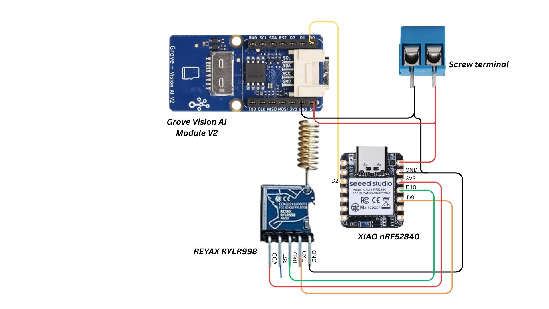
XIAO ESP32S3 + LoRa module
The Transmitter Unit is the communication backbone of our detection node.Once the detection module confirms the presence of a target animal, the transmitter’s job is to relay this information instantly and reliably to the receiver unit, even over several kilometers of dense forest or rural terrain.
At its core, the transmitter consists of a XIAO ESP32S3 paired with a LoRa transceiver module (LoRa RYLR998).
Physical Integration
- The LoRa module is connected to the XIAO ESP32S3 via UART (TX, RX, GND, and VCC lines).
- The D0 pin from the Detection Module’s XIAO ESP32S3 is wired directly to a digital input pin on the Transmitter Unit’s XIAO.
- When this pin goes HIGH, the transmitter immediately prepares and sends a predefined alert packet over LoRa.
- The wiring layout is kept short and shielded where possible to minimize signal interference from the LoRa’s RF output.
- Power delivery is handled by the same regulated supply for consistency (details in the power section).
Transmission Workflow
- Trigger Reception – The Transmitter XIAO monitors its D0 input pin
- Signal Detection – When the D0 line goes HIGH, the transmitter identifies the detected species/type based on the Detection Module’s classification output.
- Code Assignment – Each detection type is assigned a short code:
'E' → Elephant
'D' → Deer
'B' → Boar
- LoRa Transmission – The XIAO sends only the single-character code over the LoRa module (RYLR998).This keeps packets extremely small, enabling near-instant delivery and reducing the chance of transmission errors.
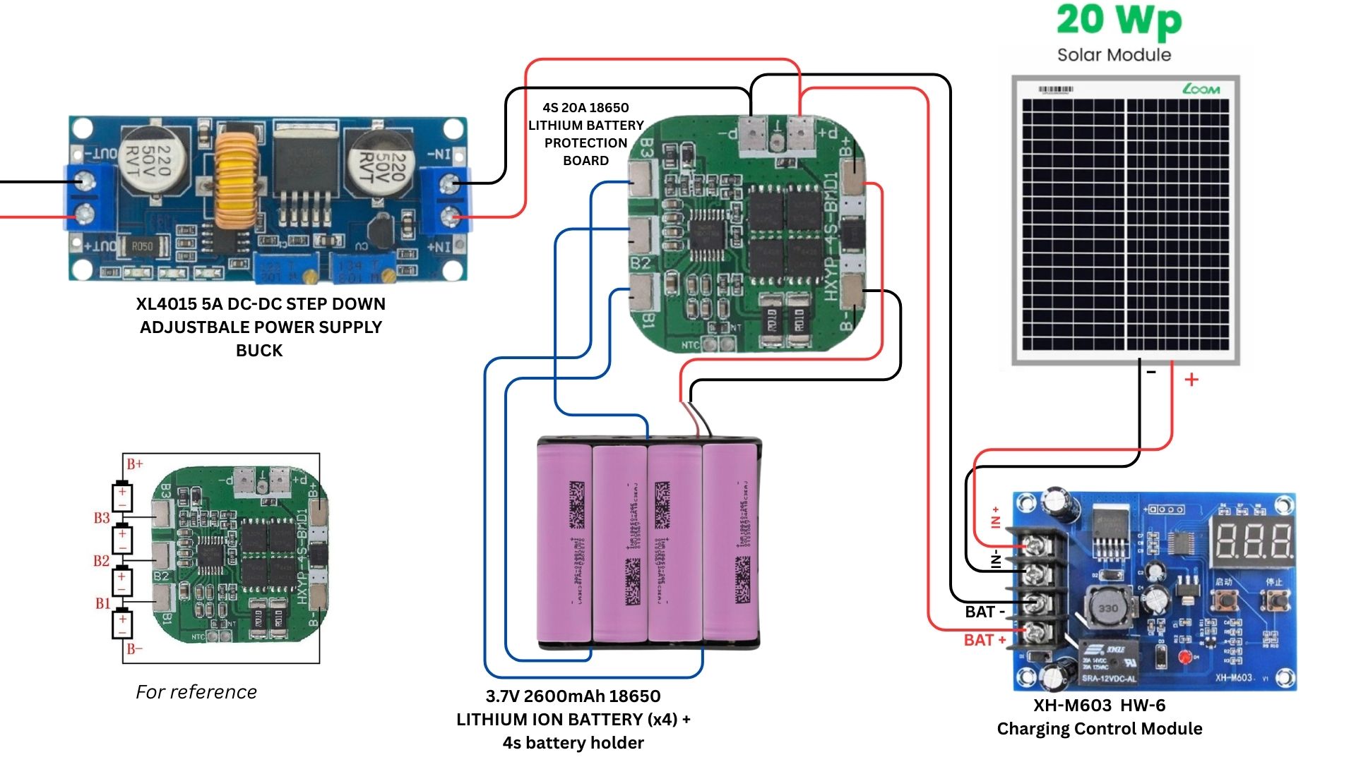
The Node unit is optimized for low-power operation, running only the XIAO ESP32S3, GROVE VISION AI V2, and REYAX RYLR998 LoRa module. A 20 W solar panel is installed to meet these requirements and ensure continuous operation in remote areas.
- Solar Input
- The 20 W solar panel generates DC voltage (~18 V peak in sunlight). - Solar Charge Controller
- A dedicated solar charge controller (MPPT/PWM type) regulates the charging process.
-Prevents overcharging, deep discharge, and reverse current leakage at night.. - Battery Pack
- A4S (series) Lithium-ion battery packis used, with a nominal voltage of 14.8 V (3.7 V × 4 cells) and max charging voltage of 16.8 V.
- A Battery Management System (BMS) is integrated for:
- Cell voltage balancing.
- Protection against overcharge, over-discharge, and short-circuits.
- Safe thermal and current operation.
- Buck Converter (DC-DC Step Down)
- The ~14.8 V battery output is stepped down to 5 V DC.
- This regulated 5 V supply powers the microcontroller and other modules.
FULL CONNECTION
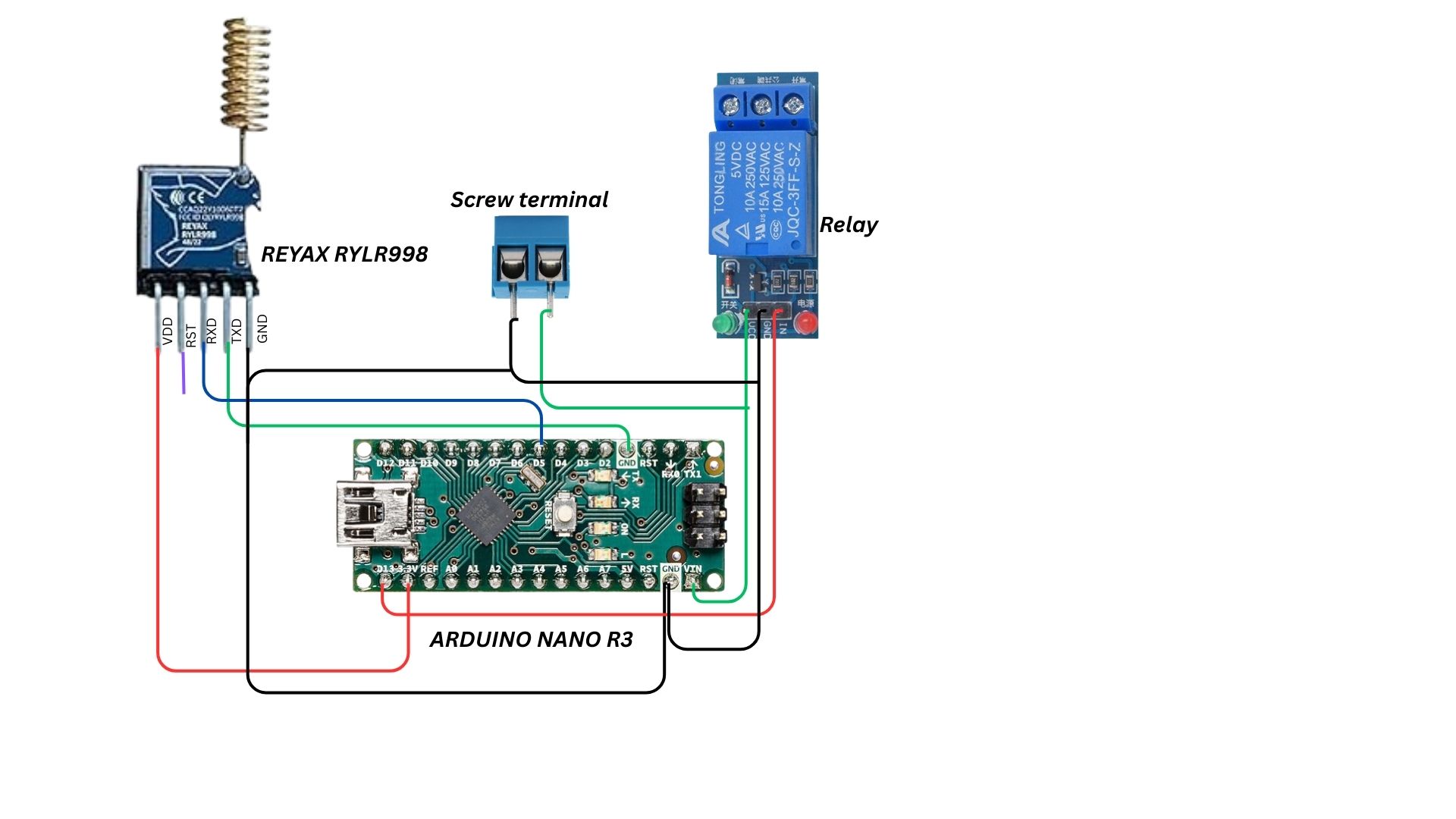
The Receiver Unit acts as the final stage in the alert chain, converting the LoRa signal from the Transmitter Unit into a real-time roadside warning.
Housed securely within the roadside post, the LoRa Communication Link Box serves as the bridge between the detection node in the forest and the roadside alert system. This contains:
- LoRa Receiver Module(REYAX RYLR998) – listens for signals sent from the transmitter node (e.g.,
'E'for elephant). - Arduino Nano – processes the incoming LoRa data and decides the appropriate alert action.
- 5V Driver Circuit – provides the necessary current and voltage to drive high-power visual alerts such as the P10 RGB LED matrix or other display units.
Now let's take a look on to the module that controls inside the Receiver unit– Arduino Nano.
Arduino NanoThe Arduino Nano is a compact yet powerful microcontroller board based on the ATmega328P.Its small form factor makes it ideal for embedding into portable or space-constrained projects while still offering all the essential features of the larger Arduino boards. In our system, it interprets incoming LoRa data and triggering the appropriate output actions.
Key Features:
- Microcontroller: ATmega328P
- Operating Voltage: 5 V
- Input Voltage (Recommended): 7–12 V
- Digital I/O Pins: 14 (6 PWM outputs)
- Analog Input Pins: 8
- Flash Memory: 32 KB (2 KB used by bootloader)
- SRAM: 2 KB
- EEPROM: 1 K
- Clock Speed: 16 MHz
- USB Interface: Mini USB for programming and power
- Dimensions: 45 × 18 mm
Pin categories
The Arduino Nano features 30 pins, divided into the following categories:
- Power Pins: These pins provide power to the board and connected components.
- Digital I/O Pins: These pins are used for general-purpose digital input and output.
- Analog Input Pins: These pins are designed to read analog signals from sensors.
- Special Function Pins: These pins have dedicated functions like communication protocols or external interrupts.
Detailed pin descriptions
Power pins:
- VIN (Pin 30): Input voltage for the board when using an external power source (7V-12V recommended).
- 5V (Pin 27): Regulated 5V power supply output.
- 3.3V (Pin 17): 3.3V power supply output.
- GND (Pins 4, 17, 27, 29): Ground connection for the board and components.
Digital I/O pins (D0-D13):
The Arduino Nano has 14 digital input/output pins. These pins can be configured as inputs or outputs and operate at 5V with a maximum current of 40mA. Some of these pins have special functions:
- Pins 0 (RX) and 1 (TX) are used for serial communication.
- Pins 2 and 3 can be used as external interrupt pins.
- Pins 3, 5, 6, 9, 10, and 11 support Pulse Width Modulation (PWM).
- Pin 13 is connected to the onboard LED.
- Pins 10 (SS), 11 (MOSI), 12 (MISO), and 13 (SCK) are used for SPI communication.
Analog input pins (A0-A7):
There are 8 analog input pins (A0-A7) that can read analog signals (0-5V) with 10-bit resolution. Pins A0-A5 can also function as digital I/O. Pins A4 (SDA) and A5 (SCL) support I2C communication.
Now that we’ve covered about the microcontroller in the receiver unit, let’s look at how the signal from the node is received at the post.
Receiver Unit OverviewInside the box fixed to the post, the receiver unit is responsible for capturing the wireless signal sent from the transmitter node and initiating the alert system at the post.
Components:
- REYAX RYLR998 LoRa module
- Arduino Nano
Operational Flow
- The LoRa module is set to continuously receive signals within the predefined frequency and network ID.
- Upon detecting a valid short-code packet, the LoRa module passes the data to the Arduino Nano.
- The received code is passed to the Arduino Nano via UART for further interpretation.
- The Arduino interprets the signal — for example,
'E'could indicate an elephant detection. - Based on the detection type, the Arduino sends a control signal to the 5V driver, which powers the LED matrix to display a warning symbol of the detected animal for approaching vehicles.
The Solar-Powered Alert Post serves as the final stage of the warning system, displaying a clear visual alert symbol to approaching vehicles when wildlife is detected. It operates off-grid, powered by a solar panel and a battery backup for nighttime or low-sunlight conditions.
Key Components
1)TP10 RGB Pixel Matrix Panels (2 units)
- Large-format, high-brightness LED display modules.
- Clear visibility in both daylight and nighttime.
- Shows animated symbols pre-loaded.
2)HD-WF1 Control Card
- Controls the LED panels.
- Stores the pre-uploaded warning symbol and displays it instantly when triggered.
3)Solar Power System + Battery Backup
- Solar Panel: Charges the battery during the day.
- Battery Pack: Ensures continuous operation at night or during cloudy conditions.


Comments