


Hardware components | ||||||
| × | 1 | ||||
Software apps and online services | ||||||
| ||||||
 |
| |||||
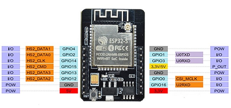
Hello everyone. In this project, an example and overview are presented showing how to upload photos in real time from an ESP32-CAM to a device on the Blynk IoT (https://blynk.cloud) platform using the new API (https://docs.blynk.io/en/blynk.cloud/device-https-api/upload-a-file).At the moment, this feature is available only to users with PRO and PRODUCTION plans.Hardware: AI Thinker ESP32-CAM
Below is an example video demonstrating the visual usage. In this specific example, a condition is triggered when the value 1 is sent to the first datastream. The ESP32-CAM takes a photo, uploads it to the server, and updates the property on pin 0. This pin is added to the Image Widget. Of course, the condition can be anything — a datastream update, an event trigger, and so on.
The solution is based on datastream properties and is available for use with all Image Widgets on the web platform, as well as in the Android and iOS applications.
The example consists of 2 files.
Please use these two files in the project folder to build the firmware.
The .ino file contains commented instructions. Please pay attention to them.
Also, please pay attention to the required libraries in the .ino file. Some of them may need to be installed in your Arduino IDE. It is also recommended to use the latest version of the Blynk library; the current version is 1.3.2.ESP32-cam-uploadphoto-Blynk.ino:
/*************************************************************
You’ll need:
- Blynk IoT app (download from App Store or Google Play)
- ESP32-CAM board
- Decide how to connect to Blynk
(USB, Ethernet, Wi-Fi, Bluetooth, ...)
Current example using Wi-Fi
*************************************************************/
/* Fill-in information from Blynk Device Info here */
#define BLYNK_TEMPLATE_ID "TMPxxxxxx"
#define BLYNK_TEMPLATE_NAME "Device"
#define BLYNK_AUTH_TOKEN "YourAuthToken"
/* Comment this out to disable prints and save space */
#define BLYNK_PRINT Serial
#include <Arduino.h>
#include <WiFi.h>
#include <WiFiClient.h>
#include <BlynkSimpleEsp32.h>
#include "soc/soc.h"
#include "soc/rtc_cntl_reg.h"
#include "esp_camera.h"
// Your WiFi credentials.
// Set password to "" for open networks
const char* ssid = "YourNetworkName";
const char* password = "YourPassword";
#define CAMERA_MODEL_AI_THINKER // Has PSRAM
#include "camera_pins.h"
// Specify your server host, for example "fra1.blynk.cloud"
String serverName = "YouServerHostName";
String serverPath = "/external/api/upload?token=" + String(BLYNK_AUTH_TOKEN);
const int serverPort = 80;
WiFiClient client;
// CAMERA_MODEL_AI_THINKER
#define PWDN_GPIO_NUM 32
#define RESET_GPIO_NUM    -1
#define XCLK_GPIO_NUM 0
#define SIOD_GPIO_NUM 26
#define SIOC_GPIO_NUM 27
#define Y9_GPIO_NUM 35
#define Y8_GPIO_NUM 34
#define Y7_GPIO_NUM 39
#define Y6_GPIO_NUM 36
#define Y5_GPIO_NUM 21
#define Y4_GPIO_NUM 19
#define Y3_GPIO_NUM 18
#define Y2_GPIO_NUM 5
#define VSYNC_GPIO_NUM 25
#define HREF_GPIO_NUM 23
#define PCLK_GPIO_NUM 22
//Specify the condition under which a photo will be taken and sent to the server
//In this case, the photo will be sent upon receipt of 1 value per virtual pin V1
BLYNK_WRITE(V1)
{
int pinValue = param.asInt();
if (pinValue == 1){
Serial.print("My pin value:");
Serial.println(pinValue);
sendPhoto();
}
}
void setup()
{
// Debug console
Serial.begin(115200);
Blynk.begin(BLYNK_AUTH_TOKEN, ssid, password);
// You can also specify server:
//Blynk.begin(BLYNK_AUTH_TOKEN, ssid, pass, "blynk.cloud", 80);
//Blynk.begin(BLYNK_AUTH_TOKEN, ssid, pass, IPAddress(192,168,1,100), 8080);
delay(3000);
WRITE_PERI_REG(RTC_CNTL_BROWN_OUT_REG, 0);
WiFi.mode(WIFI_STA);
Serial.println();
Serial.print("Connecting to ");
Serial.println(ssid);
while (WiFi.status() != WL_CONNECTED) {
Serial.print(".");
delay(500);
}
Serial.println();
Serial.print("ESP32-CAM IP Address: ");
Serial.println(WiFi.localIP());
Serial.println("INIT CAMERA");
camera_config_t config;
config.grab_mode = CAMERA_GRAB_LATEST;
config.ledc_channel = LEDC_CHANNEL_0;
config.ledc_timer = LEDC_TIMER_0;
config.pin_d0 = Y2_GPIO_NUM;
config.pin_d1 = Y3_GPIO_NUM;
config.pin_d2 = Y4_GPIO_NUM;
config.pin_d3 = Y5_GPIO_NUM;
config.pin_d4 = Y6_GPIO_NUM;
config.pin_d5 = Y7_GPIO_NUM;
config.pin_d6 = Y8_GPIO_NUM;
config.pin_d7 = Y9_GPIO_NUM;
config.pin_xclk = XCLK_GPIO_NUM;
config.pin_pclk = PCLK_GPIO_NUM;
config.pin_vsync = VSYNC_GPIO_NUM;
config.pin_href = HREF_GPIO_NUM;
config.pin_sscb_sda = SIOD_GPIO_NUM;
config.pin_sscb_scl = SIOC_GPIO_NUM;
config.pin_pwdn = PWDN_GPIO_NUM;
config.pin_reset = RESET_GPIO_NUM;
config.xclk_freq_hz = 20000000;
config.pixel_format = PIXFORMAT_JPEG;
config.frame_size = FRAMESIZE_QVGA;
config.jpeg_quality = 10;
config.fb_count = 1;
if(psramFound()){
config.frame_size = FRAMESIZE_SVGA;
config.jpeg_quality = 10;  //0-63 lower number means higher quality
config.fb_count = 2;
} else {
config.frame_size = FRAMESIZE_CIF;
config.jpeg_quality = 12;  //0-63 lower number means higher quality
config.fb_count = 1;
}
esp_err_t err = esp_camera_init(&config);
if (err != ESP_OK) {
Serial.printf("Camera init failed with error 0x%x", err);
return;
}
}
void loop()
{
Blynk.run();
// You can inject your own code or combine it with other sketches.
// Check other examples on how to communicate with Blynk. Remember
// to avoid delay() function!
}
String sendPhoto() {
String getAll;
String getBody;
camera_fb_t * fb = NULL;
fb = esp_camera_fb_get();
esp_camera_fb_return(fb); // dispose the buffered image
fb = NULL; // reset to capture errors
fb = esp_camera_fb_get(); // get fresh image
if(!fb) {
Serial.println("Camera capture failed");
delay(1000);
ESP.restart();
}
Serial.println("Connecting to server: " + serverName);
if (client.connect(serverName.c_str(), serverPort)) {
Serial.println("Connection successful!");
String head = "--Blynk\r\nContent-Disposition: form-data; name=\"upfile\"; filename=\"esp32-cam.jpg\"\r\nContent-Type: image/jpeg\r\n\r\n";
String tail = "\r\n--Blynk--\r\n";
uint32_t imageLen = fb->len;
uint32_t extraLen = head.length() + tail.length();
uint32_t totalLen = imageLen + extraLen;
client.println("POST " + serverPath + " HTTP/1.1");
client.println("Host: " + serverName);
client.println("Content-Length: " + String(totalLen));
client.println("Content-Type: multipart/form-data; boundary=Blynk");
client.println();
client.print(head);
uint8_t *fbBuf = fb->buf;
size_t fbLen = fb->len;
for (size_t n=0; n<fbLen; n=n+1024) {
if (n+1024 < fbLen) {
client.write(fbBuf, 1024);
fbBuf += 1024;
}
else if (fbLen%1024>0) {
size_t remainder = fbLen%1024;
client.write(fbBuf, remainder);
}
}
client.print(tail);
esp_camera_fb_return(fb);
int timoutTimer = 10000;
long startTimer = millis();
boolean state = false;
while ((startTimer + timoutTimer) > millis()) {
Serial.print(".");
delay(100);
while (client.available()) {
char c = client.read();
if (c == '\n') {
if (getAll.length()==0) { state=true; }
getAll = "";
}
else if (c != '\r') { getAll += String(c); }
if (state==true) {
if (c != '\n') {
getBody += String(c);
}
}
startTimer = millis();
}
if (getBody.length()>0) { break; }
}
Serial.println();
client.stop();
Serial.println(getBody);
delay(1500);
//Specify the pin and the property by which the photo will be updated.
//In the documentation you can familiarize yourself with widgets that support photos
//This example will update the offImageUrl property in Web and mobile Image Button widgets
Blynk.setProperty(V0, "offImageUrl", getBody);
//You can also specify an event code
Blynk.logEvent("event_code");
}
else {
getBody = "Connection to " + serverName +  " failed.";
Serial.println(getBody);
}
return getBody;
}
and camera_pins.h
#if defined(CAMERA_MODEL_WROVER_KIT)
#define PWDN_GPIO_NUM  -1
#define RESET_GPIO_NUM -1
#define XCLK_GPIO_NUM 21
#define SIOD_GPIO_NUM 26
#define SIOC_GPIO_NUM 27
#define Y9_GPIO_NUM 35
#define Y8_GPIO_NUM 34
#define Y7_GPIO_NUM 39
#define Y6_GPIO_NUM 36
#define Y5_GPIO_NUM 19
#define Y4_GPIO_NUM 18
#define Y3_GPIO_NUM 5
#define Y2_GPIO_NUM 4
#define VSYNC_GPIO_NUM 25
#define HREF_GPIO_NUM 23
#define PCLK_GPIO_NUM 22
#elif defined(CAMERA_MODEL_ESP_EYE)
#define PWDN_GPIO_NUM  -1
#define RESET_GPIO_NUM -1
#define XCLK_GPIO_NUM 4
#define SIOD_GPIO_NUM 18
#define SIOC_GPIO_NUM 23
#define Y9_GPIO_NUM 36
#define Y8_GPIO_NUM 37
#define Y7_GPIO_NUM 38
#define Y6_GPIO_NUM 39
#define Y5_GPIO_NUM 35
#define Y4_GPIO_NUM 14
#define Y3_GPIO_NUM 13
#define Y2_GPIO_NUM 34
#define VSYNC_GPIO_NUM 5
#define HREF_GPIO_NUM 27
#define PCLK_GPIO_NUM 25
#define LED_GPIO_NUM 22
#elif defined(CAMERA_MODEL_M5STACK_PSRAM)
#define PWDN_GPIO_NUM  -1
#define RESET_GPIO_NUM 15
#define XCLK_GPIO_NUM 27
#define SIOD_GPIO_NUM 25
#define SIOC_GPIO_NUM 23
#define Y9_GPIO_NUM 19
#define Y8_GPIO_NUM 36
#define Y7_GPIO_NUM 18
#define Y6_GPIO_NUM 39
#define Y5_GPIO_NUM 5
#define Y4_GPIO_NUM 34
#define Y3_GPIO_NUM 35
#define Y2_GPIO_NUM 32
#define VSYNC_GPIO_NUM 22
#define HREF_GPIO_NUM 26
#define PCLK_GPIO_NUM 21
#elif defined(CAMERA_MODEL_M5STACK_V2_PSRAM)
#define PWDN_GPIO_NUM  -1
#define RESET_GPIO_NUM 15
#define XCLK_GPIO_NUM 27
#define SIOD_GPIO_NUM 22
#define SIOC_GPIO_NUM 23
#define Y9_GPIO_NUM 19
#define Y8_GPIO_NUM 36
#define Y7_GPIO_NUM 18
#define Y6_GPIO_NUM 39
#define Y5_GPIO_NUM 5
#define Y4_GPIO_NUM 34
#define Y3_GPIO_NUM 35
#define Y2_GPIO_NUM 32
#define VSYNC_GPIO_NUM 25
#define HREF_GPIO_NUM 26
#define PCLK_GPIO_NUM 21
#elif defined(CAMERA_MODEL_M5STACK_WIDE)
#define PWDN_GPIO_NUM  -1
#define RESET_GPIO_NUM 15
#define XCLK_GPIO_NUM 27
#define SIOD_GPIO_NUM 22
#define SIOC_GPIO_NUM 23
#define Y9_GPIO_NUM 19
#define Y8_GPIO_NUM 36
#define Y7_GPIO_NUM 18
#define Y6_GPIO_NUM 39
#define Y5_GPIO_NUM 5
#define Y4_GPIO_NUM 34
#define Y3_GPIO_NUM 35
#define Y2_GPIO_NUM 32
#define VSYNC_GPIO_NUM 25
#define HREF_GPIO_NUM 26
#define PCLK_GPIO_NUM 21
#define LED_GPIO_NUM 2
#elif defined(CAMERA_MODEL_M5STACK_ESP32CAM)
#define PWDN_GPIO_NUM  -1
#define RESET_GPIO_NUM 15
#define XCLK_GPIO_NUM 27
#define SIOD_GPIO_NUM 25
#define SIOC_GPIO_NUM 23
#define Y9_GPIO_NUM 19
#define Y8_GPIO_NUM 36
#define Y7_GPIO_NUM 18
#define Y6_GPIO_NUM 39
#define Y5_GPIO_NUM 5
#define Y4_GPIO_NUM 34
#define Y3_GPIO_NUM 35
#define Y2_GPIO_NUM 17
#define VSYNC_GPIO_NUM 22
#define HREF_GPIO_NUM 26
#define PCLK_GPIO_NUM 21
#elif defined(CAMERA_MODEL_M5STACK_UNITCAM)
#define PWDN_GPIO_NUM  -1
#define RESET_GPIO_NUM 15
#define XCLK_GPIO_NUM 27
#define SIOD_GPIO_NUM 25
#define SIOC_GPIO_NUM 23
#define Y9_GPIO_NUM 19
#define Y8_GPIO_NUM 36
#define Y7_GPIO_NUM 18
#define Y6_GPIO_NUM 39
#define Y5_GPIO_NUM 5
#define Y4_GPIO_NUM 34
#define Y3_GPIO_NUM 35
#define Y2_GPIO_NUM 32
#define VSYNC_GPIO_NUM 22
#define HREF_GPIO_NUM 26
#define PCLK_GPIO_NUM 21
#elif defined(CAMERA_MODEL_AI_THINKER)
#define PWDN_GPIO_NUM 32
#define RESET_GPIO_NUM -1
#define XCLK_GPIO_NUM 0
#define SIOD_GPIO_NUM 26
#define SIOC_GPIO_NUM 27
#define Y9_GPIO_NUM 35
#define Y8_GPIO_NUM 34
#define Y7_GPIO_NUM 39
#define Y6_GPIO_NUM 36
#define Y5_GPIO_NUM 21
#define Y4_GPIO_NUM 19
#define Y3_GPIO_NUM 18
#define Y2_GPIO_NUM 5
#define VSYNC_GPIO_NUM 25
#define HREF_GPIO_NUM 23
#define PCLK_GPIO_NUM 22
// 4 for flash led or 33 for normal led
#define LED_GPIO_NUM 4
#elif defined(CAMERA_MODEL_TTGO_T_JOURNAL)
#define PWDN_GPIO_NUM 0
#define RESET_GPIO_NUM 15
#define XCLK_GPIO_NUM 27
#define SIOD_GPIO_NUM 25
#define SIOC_GPIO_NUM 23
#define Y9_GPIO_NUM 19
#define Y8_GPIO_NUM 36
#define Y7_GPIO_NUM 18
#define Y6_GPIO_NUM 39
#define Y5_GPIO_NUM 5
#define Y4_GPIO_NUM 34
#define Y3_GPIO_NUM 35
#define Y2_GPIO_NUM 17
#define VSYNC_GPIO_NUM 22
#define HREF_GPIO_NUM 26
#define PCLK_GPIO_NUM 21
#elif defined(CAMERA_MODEL_XIAO_ESP32S3)
#define PWDN_GPIO_NUM  -1
#define RESET_GPIO_NUM -1
#define XCLK_GPIO_NUM 10
#define SIOD_GPIO_NUM 40
#define SIOC_GPIO_NUM 39
#define Y9_GPIO_NUM 48
#define Y8_GPIO_NUM 11
#define Y7_GPIO_NUM 12
#define Y6_GPIO_NUM 14
#define Y5_GPIO_NUM 16
#define Y4_GPIO_NUM 18
#define Y3_GPIO_NUM 17
#define Y2_GPIO_NUM 15
#define VSYNC_GPIO_NUM 38
#define HREF_GPIO_NUM 47
#define PCLK_GPIO_NUM 13
#elif defined(CAMERA_MODEL_ESP32_CAM_BOARD)
// The 18 pin header on the board has Y5 and Y3 swapped
#define USE_BOARD_HEADER 0
#define PWDN_GPIO_NUM 32
#define RESET_GPIO_NUM 33
#define XCLK_GPIO_NUM 4
#define SIOD_GPIO_NUM 18
#define SIOC_GPIO_NUM 23
#define Y9_GPIO_NUM 36
#define Y8_GPIO_NUM 19
#define Y7_GPIO_NUM 21
#define Y6_GPIO_NUM 39
#if USE_BOARD_HEADER
#define Y5_GPIO_NUM 13
#else
#define Y5_GPIO_NUM 35
#endif
#define Y4_GPIO_NUM 14
#if USE_BOARD_HEADER
#define Y3_GPIO_NUM 35
#else
#define Y3_GPIO_NUM 13
#endif
#define Y2_GPIO_NUM 34
#define VSYNC_GPIO_NUM 5
#define HREF_GPIO_NUM 27
#define PCLK_GPIO_NUM 25
#elif defined(CAMERA_MODEL_ESP32S3_CAM_LCD)
#define PWDN_GPIO_NUM  -1
#define RESET_GPIO_NUM -1
#define XCLK_GPIO_NUM 40
#define SIOD_GPIO_NUM 17
#define SIOC_GPIO_NUM 18
#define Y9_GPIO_NUM 39
#define Y8_GPIO_NUM 41
#define Y7_GPIO_NUM 42
#define Y6_GPIO_NUM 12
#define Y5_GPIO_NUM 3
#define Y4_GPIO_NUM 14
#define Y3_GPIO_NUM 47
#define Y2_GPIO_NUM 13
#define VSYNC_GPIO_NUM 21
#define HREF_GPIO_NUM 38
#define PCLK_GPIO_NUM 11
#elif defined(CAMERA_MODEL_ESP32S2_CAM_BOARD)
// The 18 pin header on the board has Y5 and Y3 swapped
#define USE_BOARD_HEADER 0
#define PWDN_GPIO_NUM 1
#define RESET_GPIO_NUM 2
#define XCLK_GPIO_NUM 42
#define SIOD_GPIO_NUM 41
#define SIOC_GPIO_NUM 18
#define Y9_GPIO_NUM 16
#define Y8_GPIO_NUM 39
#define Y7_GPIO_NUM 40
#define Y6_GPIO_NUM 15
#if USE_BOARD_HEADER
#define Y5_GPIO_NUM 12
#else
#define Y5_GPIO_NUM 13
#endif
#define Y4_GPIO_NUM 5
#if USE_BOARD_HEADER
#define Y3_GPIO_NUM 13
#else
#define Y3_GPIO_NUM 12
#endif
#define Y2_GPIO_NUM 14
#define VSYNC_GPIO_NUM 38
#define HREF_GPIO_NUM 4
#define PCLK_GPIO_NUM 3
#elif defined(CAMERA_MODEL_ESP32S3_EYE)
#define PWDN_GPIO_NUM  -1
#define RESET_GPIO_NUM -1
#define XCLK_GPIO_NUM 15
#define SIOD_GPIO_NUM 4
#define SIOC_GPIO_NUM 5
#define Y2_GPIO_NUM 11
#define Y3_GPIO_NUM 9
#define Y4_GPIO_NUM 8
#define Y5_GPIO_NUM 10
#define Y6_GPIO_NUM 12
#define Y7_GPIO_NUM 18
#define Y8_GPIO_NUM 17
#define Y9_GPIO_NUM 16
#define VSYNC_GPIO_NUM 6
#define HREF_GPIO_NUM 7
#define PCLK_GPIO_NUM 13
#elif defined(CAMERA_MODEL_DFRobot_FireBeetle2_ESP32S3) || defined(CAMERA_MODEL_DFRobot_Romeo_ESP32S3)
#define PWDN_GPIO_NUM  -1
#define RESET_GPIO_NUM -1
#define XCLK_GPIO_NUM 45
#define SIOD_GPIO_NUM 1
#define SIOC_GPIO_NUM 2
#define Y9_GPIO_NUM 48
#define Y8_GPIO_NUM 46
#define Y7_GPIO_NUM 8
#define Y6_GPIO_NUM 7
#define Y5_GPIO_NUM 4
#define Y4_GPIO_NUM 41
#define Y3_GPIO_NUM 40
#define Y2_GPIO_NUM 39
#define VSYNC_GPIO_NUM 6
#define HREF_GPIO_NUM 42
#define PCLK_GPIO_NUM 5
#else
#error "Camera model not selected"
#endif


Comments