



Hardware components | ||||||
 |
| × | 1 | |||
 |
| × | 1 | |||
 |
| × | 1 | |||
| × | 1 | ||||
 |
| × | 1 | |||
 |
| × | 1 | |||
 |
| × | 1 | |||
 |
| × | 1 | |||
 |
| × | 1 | |||
 |
| × | 1 | |||
| × | 1 | ||||
| × | 1 | ||||
 |
| × | 1 | |||
| × | 1 | ||||
Software apps and online services | ||||||
 |
| |||||
Hand tools and fabrication machines | ||||||
 |
| |||||
 |
| |||||
 |
| |||||
 |
| |||||
 |
| |||||
We know that battery temperatures affect the EV performance greatly and its maintenance and optimization can increase the lifetime of the EV significantly. Nowadays commercial battery-management systems are effective but their integration and optimization is a little on the expensive spectrum. Our project demonstrates the same concept on a prototype scale as it continuously senses temperatures ands recognizes heat rising patterns and then provides liquid cooling whenever those threshold temperatures are exceeded. This will give the user immediate status indication.
Our Solution:
- There is real-time temperature monitoring happening using waterproof DS18B20 sensors.
- Automatic pump and fan control is given through a logic-level MOSFET rather than manual switching which makes it easier to monitor and control.
- OLED display and green, yellow, red LEDs along with a buzzer for showing and indicating Normal, Warning, and Critical states.
- Closed-loop reservoir → pump → water block → radiator and fan → reservoir cooling loop.
- This is an expandable concept as the same controller can monitor an EV battery pack or a critical heat zone in a conventional vehicle simply by changing sensor placement which makes it universally very useful
We started with both a fan based as well as liquid cooling concept to demonstrate real vehicle thermal management and basically to be able to show visible heat transfer. We used a mock battery in our prototype and later replaced it with silicon heating pad and used an aluminum water block. The temperature sensor measured the thermal states, and the Arduino was responsible for running the decision logic. This logic was centered on when the temperature was to cross a certain threshold then the Arduino would drive the cooling load through a MOSFET. This would then update the OLED as to what to display and the status LEDs and sound buzzer would also get triggered to indicate status changes.
Hardware and Software Assembly:- We mounted the mock battery and aluminum water block on the acrylic base and for the demo we used silicon heating pads instead of heating up real batteries.
- We then assembled the liquid loop which is, reservoir → R385 pump → water block → 120 mm radiator → back to reservoir. In the end we tightened every tube connection with a clamp
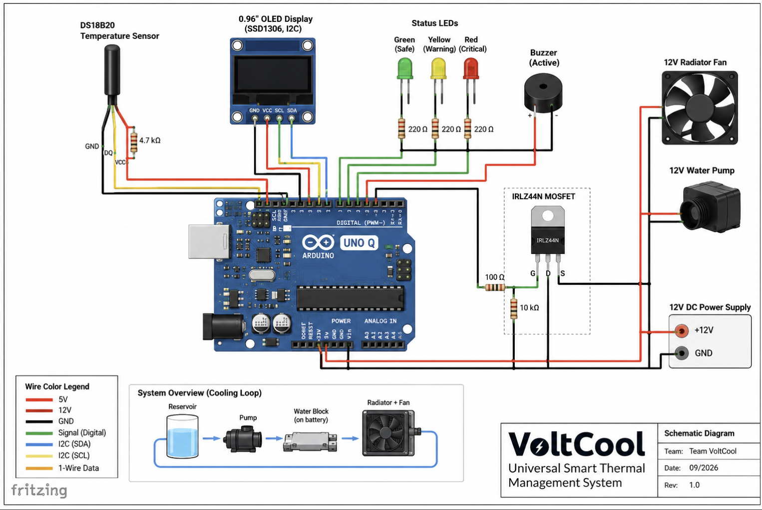
- We then wired the DS18B20 sensor to 5V, GND and D2 of the Arduino UNO Q. We added a pull-up resistor between DATA and 5V.
- Similarly, we wired the SSD1306 OLED using I2C which is VCC, GND, SDA and SCL
- We wired the green, yellow and red status LEDs through 220ohm resistors to D6, D7 and D8 and connected the active buzzer to D9.
- We used D5 as the PWM/control signal for the IRLZ44N MOSFET and this meant that the MOSFET switches the negative side of the pump/fan load and we used a common ground between the Arduino and 12 V supply.
- We then carefully created the logic for the code to control everything and after uploading it we confirmed that the OLED displayed a valid temperature before we connected it to a cooling load.
- We performed several tests starting from dry electrical tests then filling the loop to see if there was any leakage and once we confirmed no leakage was there and the electronics were protected only then we moved onto the next step.
- We then applied a controlled heat using a silicon pad which acted like a mock battery to verify that the system was progressing normally in response to a rise in temperature to the following states Normal → Warning → Critical
- We then finally recorded this demonstration with close up shots of the live temperature LEDs, pump and fan activation and cooling response of the entire system.
- Normal: This showed that temperature is in the safe demo range. Green LED turns ON and the pump/fan is OFF.
- Warning: This shows that the temperature is rising. Yellow LED turns ON and the controller starts cooling before the system becomes critical.
- Critical: This shows that the temperature is above the critical demo threshold. Red LED and buzzer activate and the pump/fan run at full cooling command.
- Recovery: This happens when the temperature falls below the thresholds, the controller automatically reduces or disables cooling and returns to Normal state.
┌──────────────────────────┐
│ 12V DC SUPPLY │
│ │
│ +12V GND │
└────┬───────────────┬─────┘
│ │
┌─────────┴──────┐ │
│ │ │
▼ ▼ │
┌────────────┐ ┌────────────┐ │
│ WATER PUMP │ │ 120mm FAN │ │
│ R385 │ │ Noctua │ │
└─────┬──────┘ └─────┬──────┘ │
│ (-) │ (-) │
└────────┬────────┘ │
▼ │
┌─────────────┐ │
D5 ───►│ IRLZ44N │ │
PWM │ MOSFET │ │
│ │ │
│ Gate Drain│ │
│ Source├───────────┘
└─────────────┘
│
GND
┌─────────────────────────────┐
│ ARDUINO UNO Q │
│ │
│ D2 ───► DS18B20 Temp Sensor│
│ │
│ D5 ───► MOSFET Gate │
│ │
│ D6 ───► Green LED ──220Ω──►GND
│ D7 ───► Yellow LED ─220Ω──►GND
│ D8 ───► Red LED ────220Ω──►GND
│ │
│ D9 ───► Buzzer (+) │
│ Buzzer (-) ───────►GND
│ │
│ SDA ───► OLED SDA │
│ SCL ───► OLED SCL │
│ │
│ 5V ─────► Sensor VCC │
│ 5V ─────► OLED VCC │
│ GND ────► Common Ground │
└─────────────────────────────┘
DS18B20 SENSOR
┌─────────────────┐
5V ───►│ VCC │
D2 ───►│ DATA │
GND ───►│ GND │
└─────────────────┘
│
4.7 kΩ pull-up
DATA ↔ 5V
OLED DISPLAY
┌─────────────────┐
5V ───►│ VCC │
GND ───►│ GND │
SDA ───►│ SDA │
SCL ───►│ SCL │
└─────────────────┘
STATUS OUTPUTS
D6 ──220Ω──► 🟢 GREEN LED ──► GND
NORMAL
D7 ──220Ω──► 🟡 YELLOW LED ─► GND
WARNING
D8 ──220Ω──► 🔴 RED LED ────► GND
CRITICAL
D9 ─────────► BUZZER (+)
BUZZER (-) ────► GND
The following is the complete BOM that shows the hardware that we selected for the liquid-cooling prototype,
Approximate total prototype cost from the final parts list: about $245.
Software:- Arduino IDE
- OneWire + DallasTemperature libraries
- Adafruit GFX + Adafruit SSD1306 libraries
- Serial Monitor for sensor/debug output
- Fritzing for the wiring diagram
D2 → DS18B20 OneWire data
D5 (PWM) → IRLZ44N gate / cooling control
D6 → Green LED
D7 → Yellow LED
D8 → Red LED
D9 → Active buzzer
SDA → OLED SDA
SCL → OLED SCL
5 V → DS18B20 and OLED logic power
GND → Common ground
Electrical Safety and Reliability Notes:- Always use a shared ground between Arduino and external 12V supply we had to find out the hard way
- Do not ever drive the pump or fan directly from an Arduino pin and use a MOSFET as a switching state
- A flyback diode is useful across inductive DC loads like pump
- Keep the liquid tubing and the reservoir physically separated from exposed electronics and always do leak testing before doing the powered thermal testing
- Use a silicon heating pad or mock battery module for demonstration purposes
The core code reads the DS18B20 and then classifies the temperature state and controls the MOSFET and pump and then triggers and updates the physical indicators. The thresholds that we used are very easy to adjust for demonstration testing.
#include <OneWire.h>
#include <DallasTemperature.h>
#include <Wire.h>
#include <Adafruit_GFX.h>
#include <Adafruit_SSD1306.h>
const int TEMP_PIN = 2;
const int COOLING_PIN = 5; // MOSFET gate (PWM)
const int GREEN_LED = 6;
const int YELLOW_LED = 7;
const int RED_LED = 8;
const int BUZZER = 9;
const float WARNING_C = 35.0; // demo threshold
const float CRITICAL_C = 42.0; // demo threshold
OneWire oneWire(TEMP_PIN);
DallasTemperature sensors(&oneWire);
Adafruit_SSD1306 display(128, 64, &Wire, -1);
void setStatus(bool g, bool y, bool r, bool alarm, int coolingPWM) {
digitalWrite(GREEN_LED, g);
digitalWrite(YELLOW_LED, y);
digitalWrite(RED_LED, r);
digitalWrite(BUZZER, alarm);
analogWrite(COOLING_PIN, coolingPWM);
}
void setup() {
pinMode(COOLING_PIN, OUTPUT);
pinMode(GREEN_LED, OUTPUT);
pinMode(YELLOW_LED, OUTPUT);
pinMode(RED_LED, OUTPUT);
pinMode(BUZZER, OUTPUT);
sensors.begin();
display.begin(SSD1306_SWITCHCAPVCC, 0x3C);
display.clearDisplay();
display.setTextColor(SSD1306_WHITE);
}
void loop() {
sensors.requestTemperatures();
float tempC = sensors.getTempCByIndex(0);
const char* state;
if (tempC < WARNING_C) {
state = "NORMAL";
setStatus(HIGH, LOW, LOW, LOW, 0);
} else if (tempC < CRITICAL_C) {
state = "WARNING";
setStatus(LOW, HIGH, LOW, LOW, 160);
} else {
state = "CRITICAL";
setStatus(LOW, LOW, HIGH, HIGH, 255);
}
display.clearDisplay();
display.setTextSize(2);
display.setCursor(0, 0);
display.print(tempC, 1); display.println(" C");
display.setTextSize(1);
display.print("Status: "); display.println(state);
display.display();
Serial.print("Temperature: "); Serial.print(tempC);
Serial.print(" C | "); Serial.println(state);
delay(500); }
Team Contribution:The team divided the project across hardware assembly and software while testing, integration and demonstration were done in collaboration.
- Predictive response: The system gives the advantage of cooling in the Warning state, before it can even reach the Critical state
- Energy-aware control: The cooling is activated only when the sensed temperature requires it and not constantly running the pump/fan
- Universal architecture: The system provides core sensing and gives decision and displays those decisions to show actuator logic. We can change the sensor placement to make it applicable for all vehicles, making it vehicle-agnostic.
- Visible engineering demonstration: The system has a liquid loop, water block, radiator, pump, sensor, control electronics, and status interface making the thermal-management process easy to understand in real time.
- Low-cost teaching platform: The system prototype demonstrates principles used in larger thermal-management battery systems with affordable and replaceable parts.
So for an EV the sensor is placed on or near the battery thermal interface and the cooling loop then removes the heat from the mock pack and for a traditional vehicle the same controller can be used to monitor a specific heat zone like the engine bay area or the radiator area or the 12 V battery enclosure area. So, the software architecture can remain the same and only the physical senor placement and cooling location needs to change for it to be used on any given vehicle.
Scaling-what we would add next to scale it to the next level:- Multiple DS18B20 sensors to calculate temperatures across the battery
- Rate-of-rise prediction (°C/min) so cooling can start based on thermal trend and not only absolute temperature.
- Wi-Fi/Bluetooth dashboard and data logging can be a user-friendly scaling factor.
- Closed-loop PWM control instead of simple threshold states.
- Fault detection for disconnected sensors, pump failure, or abnormal temperature rise.
This is just an educational prototype and not an actual automotive-qualified battery management system
- The mock battery should always remain unpowered during heating demonstrations as that’s very dangerous
- The 20–40 °C temperature range that we mentioned in our planning research is a general operating target and as real battery limit depends on cell chemistry, the manufacturer specifications, the battery pack design, the charge and discharge rate and the thermal controls
- We had to be cautious of liquid leaks, electrical shorts, sensor errors and pump failure so we took leak testing and fault handling very seriously and that helped us make improvements.


Comments