
Hardware components | ||||||
| × | 2 | ||||
 |
| × | 1 | |||
| × | 1 | ||||
| × | 1 | ||||
| × | 1 | ||||
| × | 1 | ||||
| × | 1 | ||||
| × | 1 | ||||
| × | 1 | ||||
Software apps and online services | ||||||
| ||||||
 |
| |||||
As the IoT technologies grow, they enable us to simplify our daily life and automate more and more of our routine tasks. Automating the irrigation of our trees, plants or large crop fields could be one of the many benefits of IoT. With the help of our automatic watering system, you will be able to monitor the moisture of soil and let the system "decide" and water your plants instead of you. In addition, you can see the temperature and humidity of air and have an idea about the condition of your plants. That is enough introduction. Let's get started...
Structure of the systemOkay. We now have an insight into what we are going to build. Let's see which part of the system is responsible for what. The two most essential parts are WeMos boards that connect to Cayenne platform and exchange data. I call them:
- Sensor Controller
- Valve Controller
1. Sensor Controller is just in connection with soil moisture sensor, placed in the field and does:
- Read data from soil moisture sensor
- Compare it with the THRESHOLD which is set by user
- Decide if valve should be open/closed and send it to Cayenne
- Send soil moisture to Cayenne for user to monitor it
- Accept THRESHOLD data from Cayenne
2. Valve Controller is in connection with solenoid valve and DHT11 temperature and humidity sensor. It does:
- Read data from DHT11 sensor and send it to Cayenne
- Accept data from Cayenne that states whether the valve should be closed or open(1 or 0)
- Control the valve(open or close it)
Note: I could design the system in a way that Sensor Controller would send pure sensor readings to Cayenne and triggers of Cayenne would decide the state of valve and send it to Valve Controller. It is obviously more straightforward but unfortunately, triggers of Cayenne was not good at deciding based on Analog Data and I had to find workaround for this problem. So I moved decision part to Sensor Controller.
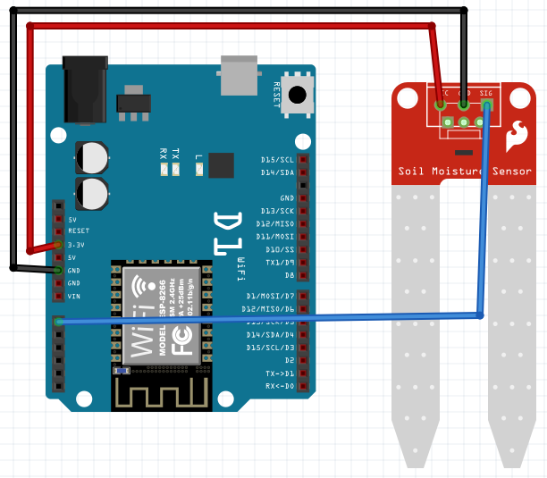
Sensor Controller connectionsLet's make the circuits! Circuit of the Sensor Controller is very simple. Just connect soil moisture sensor to the board and it is ready. But I could not prepare a proper casing for it as I have very limited tools. If you have a 3D printer and enough skills, you rock! Otherwise, I believe you are creative enough to figure out some housing for it. Anyway, just keep your device away from water!
WeMos <-> Sensor
3.3V - VCC
GND - GND
A0 - SIG
Note: Analog input of ESP8266 chip cannot handle voltages over 1V. But WeMos board increased this value to 3.3V, so we can use 3.3V sensor without any voltage divider. As far as my logic goes, if sensor works with 3.3V, it would not output more than 3.3V and it should be true for 5V sensors. Our soil moisture sensor works with both 3.3V and 5V but do not connect it directly to 5V as it might damage your board.
My Sensor Controller looks like this:
I am sure yours looks much better :)
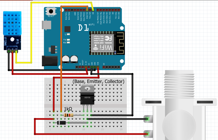
Valve Controller connectionsLet's explore this circuit with you a bit more. DHT11 sensor is again simple to use.
WeMos <-> DHT11
3.3V - VCC
GND - GND
DigitalPin - S(Signal)
Connect Signal Pin to any digital pin you want(just try to avoid D0 and D1 as they are used for serial communication with PC).
In Valve Controller sketch, make sure you change DHT_PIN to whichever pin you have connected:
#define DHT_PIN D8 //DHT temperature and humidity sensor is connected to digital pin 8
Now, let's do not rush! You should carefully connect your wires to the valve. You can use Quick Connects that you see in the picture as it is the easiest solution:
However, I would advice you to find more rigid, insulated and long cables since your valve might expose to some water and dirt. I found some common power cable from home and connect it tightly through the holes on connectors of valve and insulated it as effective as I can. Soldering them is highly recommended:
After you have successfully completed connections of your valve, we can go on with the connections on breadboard. But wait!? If you have used a power cable like mine, how are you supposed to connect it to the breadboard?
Just cut and strip off one end of some jumper wires(I wasted lots of them on this project) like you see in the picture:
And do it with your power cable before you connect them. This time soldering is "higherly" recommended because jumper wires are fragile. Insulate them and let's move on!
Phew! That was a lot of work with cables. When it comes to the rest of the diagram, it is simple transistor as a switch circuit. When you supply voltage to the base of the transistor, current will be flowing from collector to emitter. In our circuit, we put our transistor just before the Ground. Until we supply voltage to the base of transistor, it will not let the current pass to ground and, therefore, our valve will stay closed. Enough theory. Let's make it! Connect base(left leg is base in TIP121 transistor, check datasheet if you use another one) of your transistor to any digital pin through 1K resistor. This pin will control your valve. Then open Valve Controller sketch and put this pin name near VALVE variable:
#define VALVE D10 //digital pin 10 is connected to transistor which controls the valve
Note: Do not omit 1K resistor. It is used to limit the current flowing to the base of the transistor. If you directly connect digital pin to the base, too much current will be drawn and it might damage your transistor.
Now we should feed 12V to our solenoid valve. I have prepared a small diagram to show you the direction of current flow since it could be a bit confusing to understand it from schematics:
Keep in mind that voltage that comes to VIN pin of the Arduino or ,in our case, WeMos board bypasses onboard voltage regulator. So to get raw voltage that comes to DC barrel jack of the board, we should use VIN pin. In our case, if you have connected a 12V adapter to the barrel jack of your board, there will be 12V in VIN pin. Bring it to the breadboard(as you see below). For most of the 12V solenoid valves I have looked on the Web, polarity does not matter. The coil does not care which side is positive or negative. If there is nothing stated about polarity on the valve, then don't worry, just go on!
Connect one wire from the valve to 12V rail on breadboard and the other wire to the collector of transistor. Finally, connect emitter of the transistor to the Ground. There you go!
Snubber diodeThe only thing left is that diode you see in schematics. It is called snubber diode(or flyback diode) and used for safety. It is connected across the terminals of inductive loads, such as relays, solenoids and motors, which might produce transient voltage spikes after sudden power loss. Without it, those voltage spikes can damage other components of the circuit.
Snubber diode is placed in parallel to terminals of the valve and should only allow current from negative side to the positive. Since diodes allow current only in one direction(from the side with no stripe to the side with white stripe), ensure that you connect the side with white stripe to red wire side of your valve. Otherwise, there will be short circuit between 12V and GND and it can damage your board!
That is all about circuits! Before moving on to Cayenne platform, we should consider power supply of our boards.
Power supplyWhen we think about Valve Controller, it will stay in one place in some distance from the valve and should definitely have 12V power source. So 12V adapter is the best choice. Make sure it can provide, at least, 1A of current since it should power both the board and valve.
Unfortunately, we cannot say the same thing for Sensor Controller. It is supposed to be mobile. I tried it with fully charged 8.4V 3800mAh NiMH battery and it did not even last a few hours. So right now for prototyping, I connect it to 9V wall adapter which I got from my old router. If you have any idea about how to make it fully mobile, I would appreciate if you share it with us. I also read some articles about ESP8266 power consumption and seems like there is much work to be done on this side. Data could be sent between long deep-sleep intervals and as I work on it, I will update this project. I think if I can move it from prototype to higher level such as, making dedicated PCB or at least, protoboard, I will have to face with this problem more seriously.
CodeYou will need two sketches that I have included in attachments section. You will find them below. Each of them should be uploaded to corresponding WeMos board. But you also need two libraries for DHT11 sensor and I added links for them in the GitHub repository too. I would explain each piece of code here in story but I have plenty of comments in my sketches that explains everything clearly. So you just need to read the code to understand what is going on. By the way, do not forget to include your WiFi credentials and Cayenne MQTT details in sketches. To find out your Cayenne MQTT details, let's move on to the next section...
Setting up CayenneAfter you sign up in Cayenne, go to "Add New..." -> "Device/Widget" -> choose "Generic ESP8266" under Microcontrollers. You will be provided with MQTT username, password and ClientID. Copy/paste them to corresponding fields in your sketches. After you upload your code to the board and board connect to WiFi, your dashboard will appear on your screen. You will have to do this for each of your device. Now it is time to populate your dashboard.
Instead of filling here with lots of pictures that might confuse you about where is what, I recorded video showing all you need to have in your Cayenne dashboard and triggers. If you do not even know how to set up your device in Cayenne, you can always refer to Cayenne Docs: https://mydevices.com/cayenne/docs/intro/
It is a piece of cake thanks to Cayenne team. Just sign up and follow the instructions.
Demo VideoI prepared a short demonstration video to show it in real-life. I hope you enjoy it!
Implementation in large fieldsAutomatic Watering System would be a high requirement if you have a large field to be watered. So I thought about how we can implement this system in such a scenario. We would need a Water Pump and a Pressure Controller connected to it. Just in case you do not know what is pressure controller, it is a device that usually sits on top of the pump and controls it depending on the pressure in pipes.
For example, if we use it at our home, when we open a tap to wash our hand, it will automatically switch the motor on. When we close the tap, the pressure will increase in the pipe and the pressure controller will switch the motor off.
When it comes to a large plant field, pump with pressure controller would be placed at the beginning of the water pipe and the pipe would be shared among different lanes, each having its own Valve and Sensor Controller. When any of the solenoid valves is opened, pressure would drop at the pipe and pump would pump the water to the corresponding lane. Finally, when the water is reached end of the lane, Sensor Controller would be triggered and the Valve is closed, thus increasing the pressure in line and stopping the pump.
On the other hand, if your pump is not dedicated to your farming and you even have to control your pump, we already found the solution:
I already own it and carried out some experiments with this module. Even with Arduino, I was able to control domestic water system because it can handle loads up to 60 Amperes(read that again!!),not even mentioning it is under 10$. In a scenario like in the picture below, we can switch our motor on and off according to the state of valves:
It was a great fun for me to work on this project and I believe, I will be working to upgrade it. I would appreciate it if I see your thoughts about it in the comments. Thank you for bearing with me until here :)
Sensor Controller


_3u05Tpwasz.png?auto=compress%2Cformat&w=40&h=40&fit=fillmax&bg=fff&dpr=2)

Comments