


Hardware components | ||||||
 |
| × | 1 | |||
| × | 1 | ||||
| × | 1 | ||||
| × | 1 | ||||
| × | 1 | ||||
| × | 1 | ||||
| × | 1 | ||||
| × | 3 | ||||
| × | 1 | ||||
| × | 1 | ||||
| × | 4 | ||||
| × | 1 | ||||
 |
| × | 2 | |||
| × | 10 | ||||
 |
| × | 1 | |||
| × | 1 | ||||
 |
| × | 1 | |||
Software apps and online services | ||||||
 |
| |||||
 |
| |||||
Hand tools and fabrication machines | ||||||
 |
| |||||
 |
| |||||
The Arduboy FX (https://www.arduboy.com) is a nice 8bit console, with many games and a small credit card format. Its schematics is open-source, but there have been only a limited number of DIY clones in a full Arcade stick format. Hence, this project!
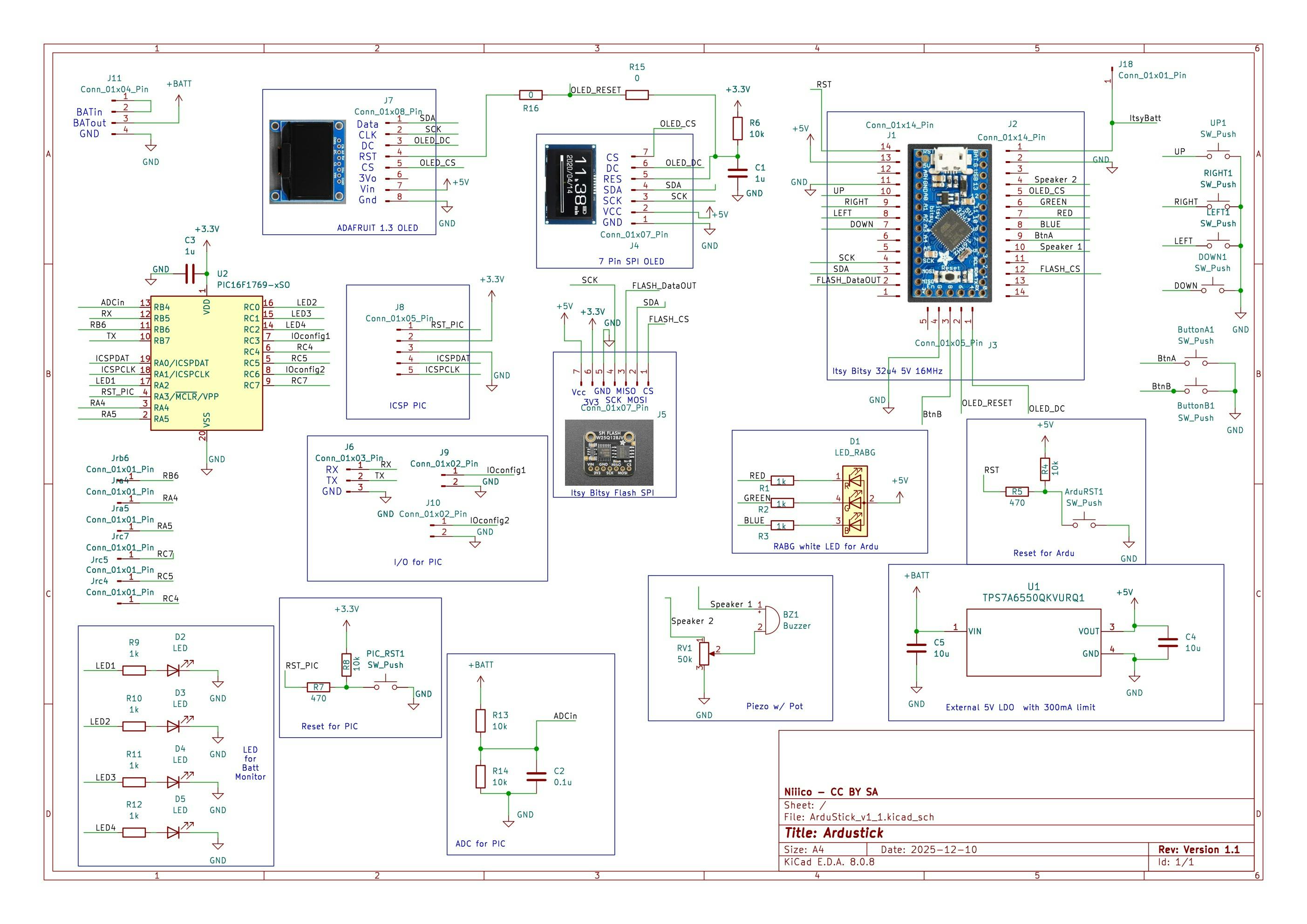
This was also done as a way to get hands on experience with some tools, such as KiCad (schematics, layout), 0805 SMD soldering, 8bit PIC microcontroller, which is added in a 8bit dual core approach to keep the Arduboy clone in its basic format but with added functions.
The main purpose is also to build a DIY Arduboy FX clone in an arcarde bartop format, with full scale arcade stick and buttons.
Main changes from the original design:
- Use a second 8bit microcontroller to monitor the battery voltage. I wanted to keep the ATmega32u4 as a “standard” homemade Arduboy, and so, I added another core - not arduino this time, but with a PIC16F family. It will read the battery voltage, scaled down with a resistor divider, then ADC and blink the 4 added LEDs to show the state of charge. The PIC16F is supplied by the 3.3V regulator from Adafruit’s Flash module I used
- USB socket to update the cart from the outside
- Swappable 2.42 inch SPI OLED screen (to change the color!) based on SSD1309
- Reset button to go back to menu, and also reset button of the PIC16F core (the small red button, that would trigger another measurement of battery voltage and blink the LEDs)
- Volume pot and Volume ON/OFF switch
- Powered by 4xAA NiMH, but can be powered by anything between 3.3 V and up to 10 V
- Bonus: the same PCB can also be used with pushbuttons directly on PCB, a smaller SSD1306 screen 1.3’, to act as a Arduboy FX clone
The schematics, pictures are licensed under CC BY SA. The videos are licensed under CC BY.
The PIC16F C code is licensed in GNU GPL v3.
Demo - See it in action!Quick demo of ArduStick with some games from the community:
Demo of the battery voltage monitor (same PCB)
Summary of building stepsFull details on the repo: https://github.com/NicoRouger/ArduStick
and https://github.com/NicoRouger/AkuMon_Software for the PIC16F microcontroller
The building steps are:
- Solder the header and Burn the Arduboy bootloader of the 5V 16 MHz Itsy Bitsy with an arduino, using https://github.com/MrBlinky/Arduboy-homemade-package
- Solder the header of the SPI Flash module, assemble the itsy bitsy and Flash module (breadboard is ok) and flash the game cartridge using https://github.com/MrBlinky/Arduboy-Python-Utilities
- Use the schematics used here
- Make the PCB layout and get it fabricated, assemble the parts
- Program the PIC16F (e.g. with snap or pickit basic programmer), and test
- Build the bartop with MDF wood: I used some left over, and made a model with cardboard
- Assemble the Stick, buttons, and screw the PCB to the bartop
- Enjoy!
One button, after burning the Itsy Bitsy and the flashing the games:
Adding the buttons, buzzer, and trying with the arcade stick:
PCB layout and fabrication. Results:
Soldering (lead free):
PCB test:
Bartop machining:
Final assembly:
Final result:
Right side: USB connector, ON/OFF switch
Left side: Sound ON/OFF, vol pot
The four small holes on the bottom right of the screen are to show the battery voltage level with the four red LEDs.
Bonus!
The same PCB can be used with a smaller OLED screen, from Adafruit (SSD1306, 1.3 inch, 8 pin SPI, here with a cardboard controller :) )
Consider some minor modifications / comments:
Pin 3 from the volume POT (RV1) must not be grounded. It should be either floating or more preferably, shorted to pin 2.
Adjust the LED resistors depending on the LEDs and desired light power.
I used sockets for the screens, Itsy Bitsy and Flash memory.
Populate only one resistance from R15 and R16, depending on the screen used. For my SSD1309, I even left R15 unpopulated, because the screen has already a pull up on RST with RC. In case of 2.42" SPI screen, R15 could also be replaced by a Schottky diode, with cathode on OLED_RESET and anode on screen RST pin.
Also the input for AkuMon "ADCin" can be clamped with a diode (pin #13, RB4 of the PIC16F). This way, there won't be any issue with a power supply input higher than 10 V and lower than 40 V.
Suggestions and possible improvementsThe bartop has been made with MDF wood, covered by a black vinyle. The layout can definitely be improved! But it works!
The portable version would appreciate some time to replace the cardboard controller :)
The battery voltage is monitored, but is significantly affected by the current drawn (e.g. game, screen usage). Nonetheless, it provides a useful feedback on the battery available charge.
Further functionalities can be added in the second core such as: total playtime logging, battery voltage log, additional data transfer,...
Many thanks to the community and past makers, who provided clear instructions and amazing tools!


Comments