

Hardware components | ||||||
 |
| × | 1 | |||
| × | 1 | ||||
 |
| × | 1 | |||
 |
| × | 1 | |||
 |
| × | 1 | |||
Software apps and online services | ||||||
 |
| |||||
| ||||||
Well, it happens... you use BOSSA or other tools to upload a new program, or to update the bootloader (e.g. for CircuitPython) and something goes wrong... maybe a wrong setting, or a wrong option (in particular, the dangerous "erase all"!), or even a power failure during the upload and... damn it, the board is now bricked!
What to do now?
Yes, you can use an SWD programmer to restore the bootloader. But if you do not have one, you can still easily restore the bootloader of your bricked board with this extremely simple project.
This project aims restore the bootloader on SAM D21 boards (uChip, Arduino Zero, Feather M0, etc.), but with small modifications it can be adapted to other kinds of target boards that use SWD (serial wire debug).
For this project, we used uChip as host, which has the advantage of being extremely compact, allowing also to directly power the target board to be restored. Furthermore, in this example, we use the uChip bootloader, to restore bricked uChip boards. If you need to unbrick other boards (e.g. Arduino Zero) you must follow the procedure to include the correct bootloader (see below).
The source uses the Adafruit DAP library, which, in turn, is based on Alex Taradovs Free-DAP. Kudos to them! Please read the copyright notice on the source!
The program simply performs the following tasks:
- Wait for a serial monitor connection (you can disable this feature if you are not interested in the debug messages and if you just want a standalone unbricker. See later in this text!)
- Unlock bootloader protection fuses.
- Chip Erase.
- Bootloader upload.
- Fuse settings: bootloader protect and disable watchdog.
- Fast LED blink in case of successful bootloader restore. Fixed LED light in case of failure.
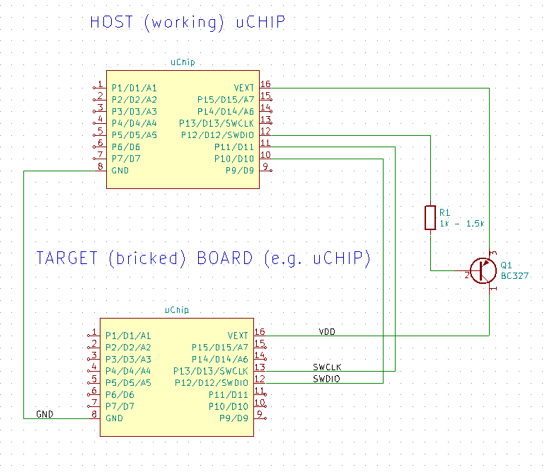
The hardware is extremely simple. The uChip drives a PNP BJT (you can of course use a pMOSFET) to power on/off the bricked board. During power-on, the SWCLK line is held low, so that the SAM D21 will wake up in debug mode.
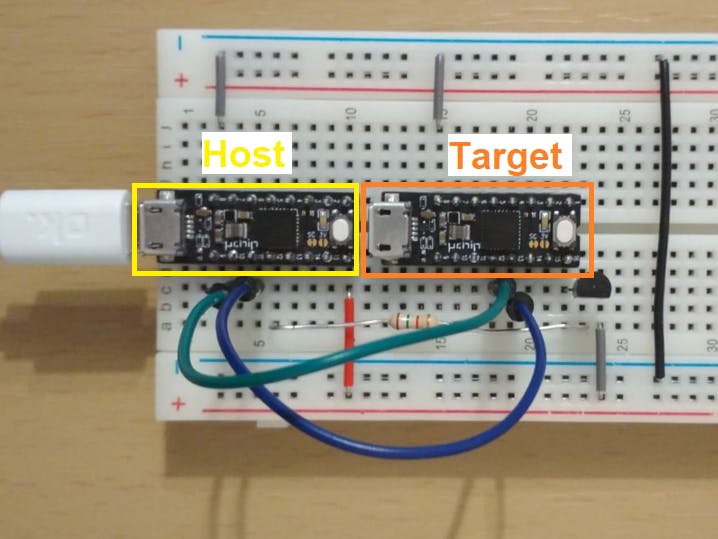
Here is the project mounted on a breadboard. Of course, you can use a perfboard/PCB with some fancy ZIF socket if you want :)
Connect to the bricked boards the lines marked as SWDIO, SWCLK, VDD and GND. In the figure above, we used uChip, therefore the pins are pin 12, 13, 16 and 8, respectively. For other boards, refer to you board's datasheet to determine where those signals are routed!
To power the system, just connect the HOST (working) uChip to an USB port, through a micro USB cable.
The software: how to unbrick another uChip boardIf you just need to unbrick another uChip board, just upload the sketch on the host uChip (the good one). Use the serial monitor to start the program. If the unbrick procedure is successful, you should see something like below:
The software: unbrick another SAM D21 boardIn this case, additional steps are required.
- Download bin2header program here.
- Put bin2header.exe and the bin file in the same directory, e.g. create a folder "BOOTLOADER" in C:\ and put bin2header.exe in
C:\BOOTLOADER - Find the bootloader of your target board. If you are using Arduino, the bootloader is stored in the
%USERPROFILE%\AppData\Local\Arduino15\packages\<vendor>\hardware\samd\<version>\bootloaders\directory. For instance for an Adafruit Feather M0, the directory is:%USERPROFILE%\AppData\Local\Arduino15\packages\adafruit\hardware\samd\1.5.4\bootloaders\featherM0(note: Windows will automatically translate%USERPROFILE%to the actual path of your user directory. For instance, if your Windows username is "johnsmith" then the above path is translated to:C:\Users\johnsmith\AppData\Local\Arduino15\packages\adafruit\hardware\samd\1.5.4\bootloaders\featherM0 - Copy the bootloader (it must have a.bin extension!) in the previously created folder (e.g.
C:\BOOTLOADER). For example, to restore a Feather M0, choosebootloader-feather_m0-v2.0.0-adafruit.5.bin - Open a command line (press the Windows key and "R" and write there
cmd, and press enter). The DOS command line window will appear. - Write there the following two commands:
CD C:\BOOTLOADERbin2header bootloader-feather_m0-v2.0.0-adafruit.5.bin(of course instead ofC:\BOOTLOADERandbootloader-feather_m0-v2.0.0-adafruit.5.binyou must put the folder name and the bootloader file name you have chosen!) - Now in
C:\BOOTLOADER(or whatever was your directory) you'll find a new file: In our case was:bootloader_feather_m0_v2.0.0_adafruit.5.bin.h(notice the added ".h" extension). - Open this new file with a notepad or whatever text program you like. (Context, Notepad++, etc.) In our case we used Context.
- Select everything and copy it (Ctrl-C)
- Now open the Arduino Sketch, and find the bootloaderBIN.h tab
- Delete everything, and paste the content you copied from the previous file (Cltr-V) - You can do this in a single step by pressing Cltr-A and then Cltr-V.
- After "
static const unsigned char" on line 3, change the varialble name (in our case it wasbootloader_feather_m0_v2_0_0_adafruit_5_bin) to "binfile"
- Upload the sketch to the host uChip.
Now your unbricker is ready for the Feather M0!
Standalone unbrickerIf you simply want a standalone unbricker (i.e. you do not want to open every time a serial monitor), you can comment out or delete the line: "#define WAIT_FOR_SERIAL_MONITOR".
Warning, if you comment or delete that line, you'll probably won't be able to see any message from the serial output, as the program will not wait for the serial monitor to open and it will be too fast.
Further improvements and final considerationsThere is a lot of room for improvement. For instance you might add 3 LEDs, red, yellow, green, to notify the status: fail, under process, pass, respectively.
You also might want to turn off the target board if you need to unbrick a lot of devices, so you can leave the host uChip powered on, and safely connect/disconnect the target board after it has been successfully unbricked.To do this add at the end of the loop function: digitalWrite(PWR,HIGH);
Furthermore, you could connect an LED (of course in series to a current limiting resistor) from VDD to GND. This will tell you when the target board is actually powered on. Furthermore if you really screwed up your board (e.g. you fried them by feeding the 230V AC mains...), a series fuse should be placed between the collector of Q1 and the VDD line of the target board.
As a last remark, this tool can unbrick the boards in which the problem is just a corrupted firmware: it cannot do miracles, so if you fried your board, well, there is nothing you can do!


Comments