

Hardware components | ||||||
| × | 1 | ||||
| × | 12 | ||||
| × | 12 | ||||
| × | 12 | ||||
| × | 1 | ||||
| × | 1 | ||||
| × | 13 | ||||
| × | 1 | ||||
 |
| × | 1 | |||
 |
| × | 12 | |||
 |
| × | 12 | |||
| × | 12 | ||||
| × | 2 | ||||
| × | 4 | ||||
 |
| × | 1 | |||
| × | 1 | ||||
| × | 4 | ||||
Software apps and online services | ||||||
 |
| |||||
Hand tools and fabrication machines | ||||||
 |
| |||||
note! This project is kept up to date on next-hack.com!
IntroductionSometimes controlling various kind of loads using a PC/Mac is desirable: one can choose his/her preferred high level language, programming environment. Loads can be easily and inexpensively switched using relays.
However, one must put some kind of interface between relays and the PC.
An USB-controlled board is a very advantageous solution: you can hook it up to any PC/Mac with an USB port and it also can draw directly the required power from it.
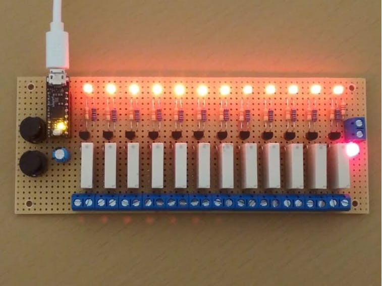
This very simple project allows you to control up to 12 relays. The chosen relays allow to switch (resistive) loads up to 3A. If heavier loads must be switched, then one can either put a more rugged relay, or can use these relays as a switch, to control bigger relays close to the loads.
The current consumption with all the relays in ON state is less than 350 mA, so any standard 500-mA USB compliant port should be adquate.
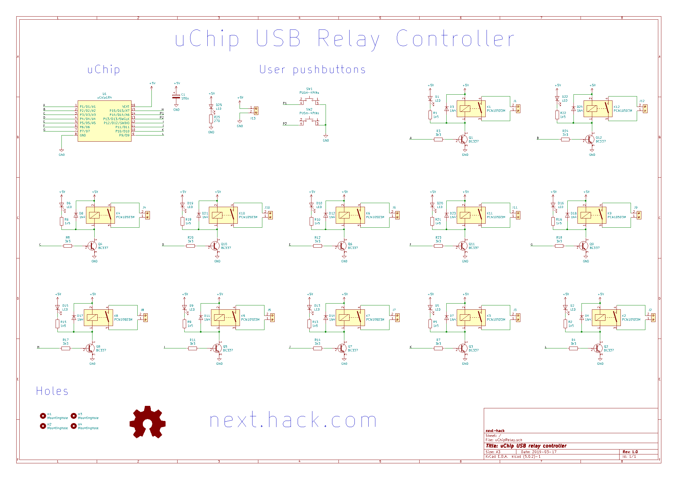
We used uChip, which is an Arduino Zero compatible board shrunk to a 16 DIP package. This allows us to make a compact design.
Two pushbuttons are added to extend the functionality of the board (e.g. emergency shutdown, sequence ecc...) These functionalities are left open to your immagination!
Theory of operationThe device waits for a serial connection on the USB port (CDC). Once a connection has been established, it periodically listens for commands.
The commands are as follows:
Capital letters A to L select the relay(s) you want to turn on or off. For instance ACF will select the first, the third, and the sixth relays. A subsequent 0, will turn off all the selected relays. A subsequent 1 will turn the selected relays on. Any other characters (including lower case a-l and 2 etc.) will abort the command.
For instance "ACF1" will turn on relays A, C and F.
If we write "CF0", the relays C and F will be turned off.
Any combination of relays can be turned on/off simultaneously.
Each relay is connected to uChip using a BJT. The LEDs show the state of the channels.
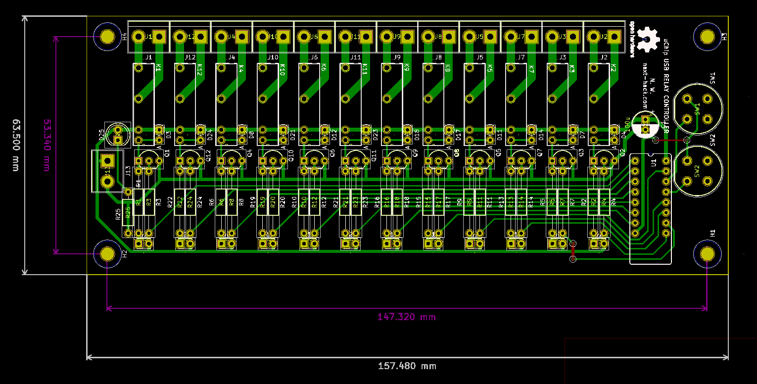
PreparationIn these steps we use a 10x16 cm perfboard. Of course, you can also manufacture the PCB following the layout.
1) Measure 6.35 cm on the perfboard.
2) Cut the perfboard along the line.
3) Use a file to smooth the edges.
4) Mark the position for the holes.
SAFETY WARNING! If using 110-240 V loads, then place the holes a bit farther than what's shown here, especially near the screw terminal blocks. Alternatively do not use metal stand-off, but plastic ones as suggested in the component list.
5) Drill the holes.
6) Solder all the components, in order of height. Resistors, IC socket, BJTs, diodes, 5-mm LED, screw terminal blocks, capacitor, the other LEDs, relays, pushbuttons.
Keep the component leads. These will be useful later for the connections!
7) After soldering the components, remove the extra pads around the relays and screw terminal blocks, ti improve insulation. This can be done using the soldering iron. Be sure to use a sacrificial tip and not your good one!
8) Make the connections using the wires you cut from the components. Use additional wire when no space is left. :-)
9) Insert uChip, connect the board with a microUSB cable and program uChip using the sketch provided and Arduino IDE.
10) Use your favourite terminal program (serial monitor, termite, etc.) and write a test string to see if it works. For instance, entering ABCDEFGHIJK1 will cause all LEDs will turn on.
11) Enjoy!


Comments