

Hardware components | ||||||
| × | 1 | ||||
| × | 1 | ||||
| × | 2 | ||||
| × | 1 | ||||
| × | 1 | ||||
| × | 4 | ||||
Software apps and online services | ||||||
| ||||||
| ||||||
Hand tools and fabrication machines | ||||||
 |
| |||||
Welcome to my first autonomous mobile robot (AMR) build. In this post, I share about the AMR system as a whole, the details of the components, and what you will need to replicate the build. I also shared some lessons learned since there’s always room for improvement.
ALBRT is an Autonomous, Lidar-based, Robot Teleoperation. This means that it is capable of doing autonomous navigations utilizing LiDAR as its main perception and also capable of being controlled by users.
This build will not dive into the theoretical aspects like the algorithms or explanations of how the details work. It is meant to help you get an understanding of how each component works for the hardware and software end. I have attached plenty of additional resources used during my build and they have certainly helped me a lot.
This is NOT your typical beginner’s tutorial that teaches you the theory and details behind it!! It, however, will get you quickly started on owning your first mobile robot 😀
Besides, there are plenty of theoretical tutorials out there… but seldom teach you hand-by-hand how to build one.
Here’s a quick demo of what can ALBERT do:
https://www.youtube.com/shorts/9qu54Y2Ln7U
https://www.youtube.com/watch?v=HbJkdnO85ss
AMR can have different sensor suits, and LiDAR is often a common sensor used. The high-level capability is that you can use LiDAR (2D or 3D) to generate the environment around the robot, once you gain this understanding, you can navigate around the environment. The technique is often called SLAM (Simultaneous Localization and Mapping).
In addition, for the robot to understand its traversal, you need some kind of Odometry that senses your change in position over time (motion). While most common design uses motor encoders to detect velocity and integrate it over time for the position, I decided to just use pure Lidar-Odometry and see the performance outcome.
This is also why part of the goal for this build is to make it as budget-friendly as possible!! But later on, I realized some of the design mistakes and how some of these could have been avoided. Nevertheless, this was a great experience and a challenge to start.
** TOO DIFFICULT??? You don’t need to get to the autonomous portion, you can just build up to the hardware component and use it for other purposes.**
Basic understanding of ROS 2
- Basic understanding of ROS 2
You will run ROS 2 on a Raspberry Pi and your laptop (ideally Linux OS)
- You will run ROS 2 on a Raspberry Pi and your laptop (ideally Linux OS)
Basic understanding of electric circuits and wiring/soldering skills
- Basic understanding of electric circuits and wiring/soldering skills
Basic programming skills
- Basic programming skills
** A determination to get the robot running no matter how long it takes! 😀 **
- ** A determination to get the robot running no matter how long it takes! 😀 **
(See BOM Section)
**Notes on battery choices: I tested several portable battery banks, the AsperX 10000 mAH and 20000 mAH are the ones that worked best for me because they don’t turn off by themselves. (Some battery power banks turn off the pi randomly possibly due to the current draw).**
“It is a good idea to always check for prices on Amazon… You can use camelcamelcamel.com to check specific Amazon items and their historical prices to make a purchasing decision.“
Before we begin the build, you should already have an OS installed on your Raspberry Pi. I will be using Ubuntu 22.04 LTS installed via Raspberry Pi Imager. Bonus point if you already have ROS 2 installed in this OS! Otherwise, check the Downloadable Content section of this post.
Hardware PreparationLet’s begin building the hardware.
Fig 2. Exploded view of hardware components
The lower-level chassis is composed of motors and motor drivers
- The lower-level chassis is composed of motors and motor drivers
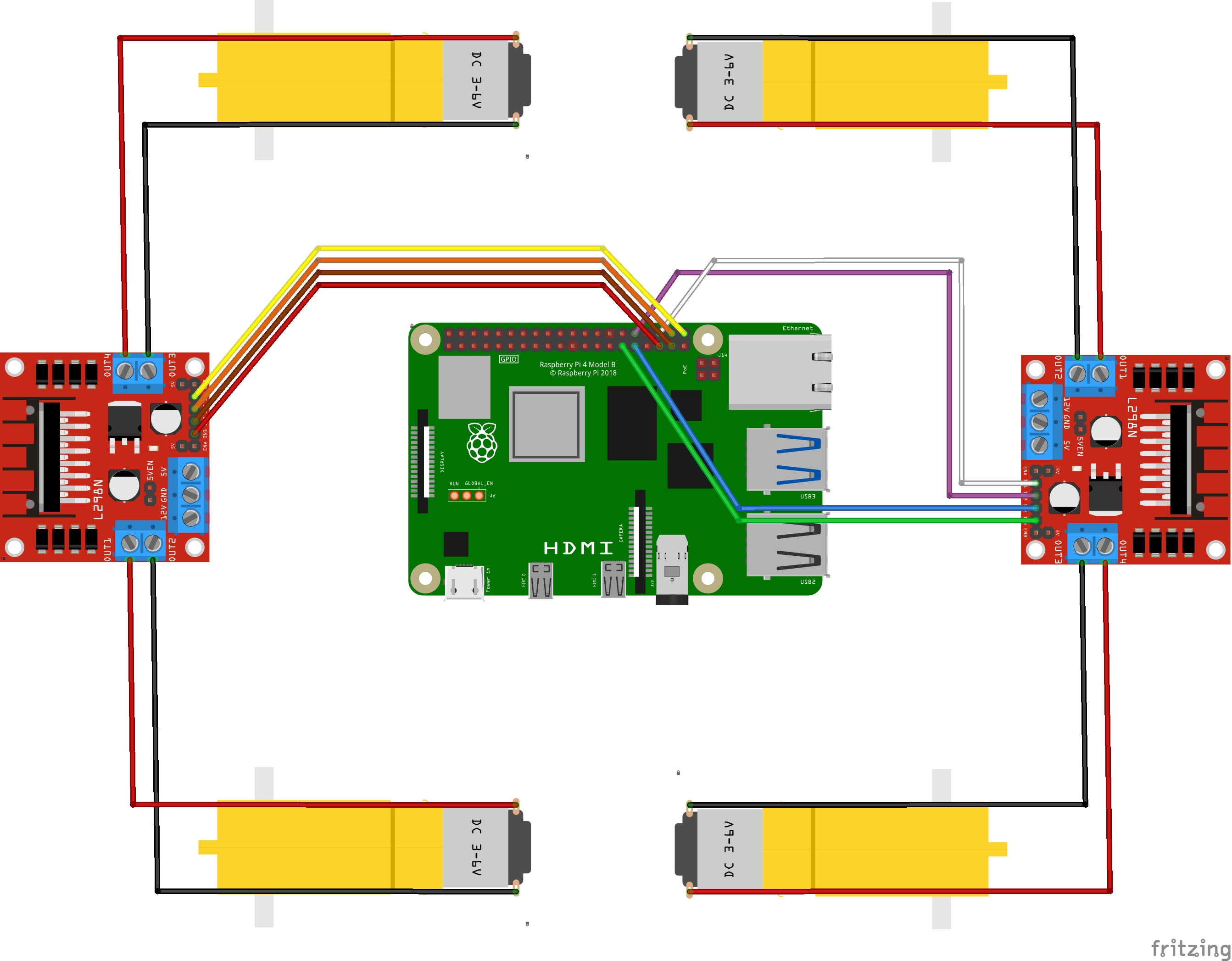
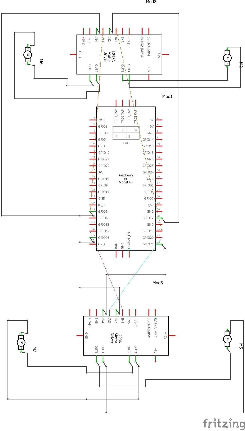
Fig 3. Circuit diagram for ALBRT
If you need to check your motor wiring and spinning direction, please see the Software Preparation section. (pin numbers and layout are also in the code).
“It’s a good idea to check your motor spin direction when you first wired it up, and use markers to label the directions”
Fig 4. GPIO example of Raspberry Pi 4
2. The mid-level of the chassis consists of Raspbery Pi and the power bank. You can be as creative as you want in the spacial configuration of the two.
3. Install the LiDAR at the top-level of the chassis. Putting at the very top avoids having obstructions to the LiDAR by the robot itself.
And that’s really it for the hardware component!! Great job so far.
Software PreparationFig 5. Example of mapping with LiDAR in Rviz using Nav2 package.
There are two devices you will need to setup:
Raspberry Pi
- Raspberry Pi
A Laptop running ROS 2
- A Laptop running ROS 2
We will begin by installing the needed ROS 2 packages available here: https://github.com/Genozen/ALBRT-1
git clone https://github.com/Genozen/ALBRT-1 # clone the ALBRT repo
cd ros2_ws # change directory to the ros2 workspace
colcon build --packages-select rplidar_ros2 my_first_robot # building the RPlidar ROS 2 driver package
The “rplidar_ros2” is the ROS 2 driver for the LiDAR, and the “my_first_robot” is to use the modified joystick listener (aka, Keyboard) to drive ALBRT.
To start scanning the environment with the LiDAR and publish the “/scan” topic:
sudo chmod a+rw /dev/ttyUSB0 # modifies the permission of the device file, in this case to be able to read/write to the serial port our lidar is connected to

source install/setup.bash # configure your current shell/terminal to ROS 2

#ros2 launch rplidar_ros view_rplidar.launch.py
ros2 launch rplidar_ros rplidar.launch.py # launches without Rviz

# run  rviz2 on the terminal if you need to visualize it
# run below if you are not seeing lidar scan in Rviz even after changing the Fixed Frame

ros2 run tf2_ros static_transform_publisher 0 0 0 0 0 0 base_link laser
To start driving ALBRT around, you have two options: 1. Use the keyboard_controller.py or 2. joystick_listener
The keyboard_controller.py would be the fastest to test and drive (you probably already used it to test your motors with this already), but simply find where the script is and run python3 keyboard_controller.py then use the arrow keys or numpads to drive it around.
The joystick_listener can be initiated by:
cd ~/Desktop/ros2_ws

sudo pigpiod

# source /opt/ros/humble/setup.bash
source install/setup.bash

# modified version of joystick listener
ros2 run my_first_robot joystick_listen
“Be sure to setup your Raspberry Pi with the same WiFi as your Laptop, otherwise they won’t be able to communicate with each other. You will also need to enable SSH onto RasPi.”
Almost done!!!
You should now be able to drive ALBRT and see the LiDAR scan (pointcloud).
Now, let’s move on to the Laptop portion. By integrating Nav2 package and some localization algorithms using LiDAR, we can then achieve autonomous driving!
# make a directory for lidar odometry package
mkdir -p ros2_ws

# change directory to the workspace
cd ros2_ws

# Install LiDAR-based Odometry  rf2o_laser_odometry
git clone https://github.com/MAPIRlab/rf2o_laser_odometry.git

#build the package
colcon build

#source ros2
source install/setup.bash

# sanity check, test run the code
ros2 launch rf2o_laser_odometry rf2o_laser_odometry.launch.py
One more thing, in the “src/rf2o_laser_odometry.launch.py” , you will need to change the setting of the “laser_scan_topic” to listen to “/scan” (You can also replace the file with the one I posted on GitHub).
Also, at the time of this tutorial, there was a bug in the “CLaserOdometry2DNode.cpp”. You will need to comment out the initialize pose, and add the following (also see GitHub for the corrected example):
GT_pose_initialized = true;
initial_robot_pose.pose.pose.position.x = 0;
initial_robot_pose.pose.pose.position.y = 0;
initial_robot_pose.pose.pose.position.z = 0;
initial_robot_pose.pose.pose.orientation.w = 0;
initial_robot_pose.pose.pose.orientation.x = 0;
initial_robot_pose.pose.pose.orientation.y = 0;
initial_robot_pose.pose.pose.orientation.z = 0;
Great, now we can utilize LiDAR to calculate the robot’s pose (position)
We will install two more things: 1. slam_toolbox, 2. Nav2
sudo apt install ros-humble-slam-toolbox
sudo apt install ros-humble-nav2-bringup
The SLAM stands for Simultaneous Localization and Mapping, and it’s exactly what it sounds like, it will calculate the robot’s position and map its surroundings!
We then coupled with the Nav2 bring-up so that we can let ALBRT do obstacle avoidance, path planning, and motion controls to the goal poses!
Let’s quickly recap.
On your laptop you should run these things:
ros2 launch teleop_twist_joy teleop-launch.py # For manual drive

ros2 launch rf2o_laser_odometry rf2o_laser_odometry.launch.py

ros2 run slam_toolbox async_slam_toolbox_node --ros-args --params-file ~/Desktop/my_
custom_config.yaml

ros2 launch nav2_bringup navigation_launch.py use_sim_time:=false

ros2 run tf2_ros static_transform_publisher 0 0 0 0 0 0 base_link laser
Fig 6. Final output of the TF tree
On Raspberry Pi, you should be running these:
ros2 launch rplidar_ros rplidar.launch.py # launches without Rviz
ros2 run my_first_robot joystick_listener
Congrats! You have finished the full setup!!!
Now, go ahead and have some fun driving it!!
Downloadable ContentsGitHub: https://github.com/Genozen/ALBRT-1
Lessons LearnedThis section is probably the most valuable thing you can get out of this post, as I share my mistakes and learnings to help readers avoid rookie mistakes and inspire them to think outside the box!
Wheel encoders
- Wheel encoders
Always adapt to use wheel encoders as the base localization method, this is by far the cheapest and somewhat reliable sensor if your robot goes slow and the environment you are in is not rough. It’s also good when you start incorporating other localization techniques like Lidar or vision-based Odometry. In short, I wish I had added some wheel encoder so I could easily fuse/combine my LiDAR and Wheel Odometry together and make the location tracking more robust!
- Always adapt to use wheel encoders as the base localization method, this is by far the cheapest and somewhat reliable sensor if your robot goes slow and the environment you are in is not rough. It’s also good when you start incorporating other localization techniques like Lidar or vision-based Odometry. In short, I wish I had added some wheel encoder so I could easily fuse/combine my LiDAR and Wheel Odometry together and make the location tracking more robust!
Lidar stability
- Lidar stability
My CADing skill isn’t top-notch and this is just being a little lazy on the 3D printed parts, but you should always stabilize your sensors (IMU, Camera, LiDAR, etc.). For a 2D Lidar, even some minor tilt and wobble will ruin your mapping and localization capabilities if you do not incorporate any noise rejection from the hardware/software end. So, be sure to stabilize your sensors as much as possible!
- My CADing skill isn’t top-notch and this is just being a little lazy on the 3D printed parts, but you should always stabilize your sensors (IMU, Camera, LiDAR, etc.). For a 2D Lidar, even some minor tilt and wobble will ruin your mapping and localization capabilities if you do not incorporate any noise rejection from the hardware/software end. So, be sure to stabilize your sensors as much as possible!
Documentation
- Documentation
This is writing to my future self, and good practice as an Engineer overall. ALWAYS document things, even just a screenshot or copy-paste, your future self will thank you later. Oftentimes, the build will get bigger, and over time you will tend to forget the exact steps taken or the libraries or the code you’ve used. Use version control, use Notion, they are your best friend.
- This is writing to my future self, and good practice as an Engineer overall. ALWAYS document things, even just a screenshot or copy-paste, your future self will thank you later. Oftentimes, the build will get bigger, and over time you will tend to forget the exact steps taken or the libraries or the code you’ve used. Use version control, use Notion, they are your best friend.
Pre-made vs DIY
- Pre-made vs DIY
Building any robot on your own is valuable and can significantly reduce the cost. Your time is also valuable, so depending on everyone’s situation, buying an off-the-shelf robot might be a better option, if building the hardware isn’t your main interest. I do think every roboticist should at least build one type of robot and integrate the hardware and software components as it will help solidify your understanding of the robotic system as a whole.
- Building any robot on your own is valuable and can significantly reduce the cost. Your time is also valuable, so depending on everyone’s situation, buying an off-the-shelf robot might be a better option, if building the hardware isn’t your main interest. I do think every roboticist should at least build one type of robot and integrate the hardware and software components as it will help solidify your understanding of the robotic system as a whole.
Power distribution
- Power distribution
Robots are power-hungry, so the power distribution is challenging. Thankfully, most handheld computers like Raspberry Pi and NVIDIA Jetson pack a ton of capabilities. Although, sometimes they might be overkill. For example, motor controls and reading high-frequency sensor data (like an IMU) or low throughput data (like a GPS) might be best suited if I integrate a microcontroller (MCU) because often these MCUs can run at a lot higher processing speed (KHz, MHz, GHz…). It will also save a lot of computational power from the main brain (Raspi, Jetson) for higher-level algorithms computation like localization, mapping, and computer vision algorithms.
- Robots are power-hungry, so the power distribution is challenging. Thankfully, most handheld computers like Raspberry Pi and NVIDIA Jetson pack a ton of capabilities. Although, sometimes they might be overkill. For example, motor controls and reading high-frequency sensor data (like an IMU) or low throughput data (like a GPS) might be best suited if I integrate a microcontroller (MCU) because often these MCUs can run at a lot higher processing speed (KHz, MHz, GHz…). It will also save a lot of computational power from the main brain (Raspi, Jetson) for higher-level algorithms computation like localization, mapping, and computer vision algorithms.
In addition, you should carefully design power distribution to different sensors and motors, as well as to your computer. The requirements are often different.
- In addition, you should carefully design power distribution to different sensors and motors, as well as to your computer. The requirements are often different.
Here are some additional resources and videos that helped me.
Articulated Robotics: Building a mobile robot playlist
- Articulated Robotics: Building a mobile robot playlist
Sunny Jaiswal: How to build a remote control car using Raspberry Pi
- Sunny Jaiswal: How to build a remote control car using Raspberry Pi
Kyle Fazzari: Your first robot, part 2: Intro to ROS
- Kyle Fazzari: Your first robot, part 2: Intro to ROS
Interface L298N DC Motor Driver Module with Arduino
SLAMTEC RPLIDAR A1: Dev Kit User Manual
How to remote access to your Raspberry Pi via SSH
Muhammad Luqman: Understanding YAML Parameters for Planners, Costmaps, and Velocities
- Muhammad Luqman: Understanding YAML Parameters for Planners, Costmaps, and Velocities

Comments