

Hardware components | ||||||
 |
| × | 1 | |||
| × | 1 | ||||
pslide
began to work on creating the final linear stage with acrylic.
The acrylic rails were done and started working on the mounting plate
The mounting plates were cut.
After many tests, created a press-fit comb to figure out the ideal slot thickness, A snapping tooth feature of the snap-fit mechanism was arrived at, and the spacers for the mounting plates were cut.
Looked for possible options for controllers that can be fabricated in house. Still waiting for the gestalt stepper nodes to arrive. continued with efforts on the linear slide. The spacers needed some more modification to make more space for parts of things like screw or snapfit clamps to fasten motor or end effector would be accommodated better between the mount plate and the rail. Also designed clamps to cover the pointy edge of the shaft(broken roland bit) so that it doesnt hurt anyone while handling.
The fully assembled linear stage.
The motions were not as smooth as I wanted it to be. I added two sheets of paper in between the top most layer and the middle and the it was smoother but still used to get stuck at certain places. It was due to the conical beam resulting in bevel cut that was causing the problem. If the wheel and the middle acrylic sheet were positioned such that the bevel of the wheel complements the bevel in the sheet cutting it could improve the performance, and that is what happened. The slide showed better movement when the the mechanisms are compensated for the bevel. The angle of laser cutting from the wheel cancelled the angle of the cut from the slide. The movement improved a lot but this system could not be deemed perfect.
Now looking for various option for transmission and positioning. salvaged timing belts from the printer. These were very thin and was skeptical about the loads it could take, but considering didnt have much load to be transferred.didnt have that smooth a linear slide and had to design the pulleys for the belt too. The tooth of the timing belt was very small which would make it prone to slipping.
Then started working on a concept of motor mounting which doesnt use the m3 threads that are available in the motor to mount.Locally its hard to find metric fasteners. A acrylic pressfit cage holding the motor and pressfit on a another acrylic plate that is mounted on the linear slide using the inch screws. So used inch screws because the linear slides were already fabricated and there were no provision to attach this. The idea is that the friction in the preffit which is pressfit over a large surface area would be sufficient clamping force for the motor to stay put.
Motor clamp was cut. Although it was easy to fabricate, the acrylic shatters easily and in some direction it is very weak. The acrylic gave a tight fit but some of them shattered because of carelessness in assembling them together. But still able to create the cage with broken yet functional pieces. designed a timing pulley that could be cut by laser. The problem was that the belt could easily slip the timing pulley. Have to think of another transmission system or get a better belt and pulley system. Experimenting on fabricating these could cost us more time, was thinking of finally buying these stuff.
Figuring out what transmission to use.Couple of feasible options other than the belt -rack and pinion.Cable drive/capstan mechanism.Just decided to work parallel for both mechanism.Needed to test driving mechanism for the linear stage, test and improve the main mechanical frame, test extrution, fix the belts on the mechanical frame and test the motions, figure out the kinematics of the machine, control the machine using cnc controller, send g code and confirm the motion.
The capstan mechanism would work similar to whats shown here https://www.youtube.com/watch?v=sXl1Ei3O2hA.
The use of double sided tape a good prototyping fastener to check the positioing, assembly and dimensions of a flat surfaces became very obvious and used it extensively to put together stuff quickly.
Pulley - 3d printed problems faced- strength in direction- if printed legth direction alligning a direction- breaks easily. The design could be better in order to reduce the cantilever action. The Pulley could be placed in a way that aligns the layer favourable to force/ moment applied
Further
Driving mechanism
Rack and pinion: Used http://hessmer.org/gears/InvoluteSpurGearBuilder.html to generate the rack and pinion.Tried to keep the teeth numbers more, tooth length less so that it is strong even if it is acrylic and the gear profile to be around the radius of 11mm so that can place the rack and pinion assembly between the mount plate and the motor. For the pinion 3D printing was also a good option.
Problems:Bending of the rack- Can cause backlash and sliping and unreliable distance moves. Solved by adding a piece of acrylic in between the rack and mounting plate. This piece(yellow in color in the pictures above) slides on the rack and keeps the rack and pinion engaged. Backlash- There will be backlash always when using a simple rack and pinion attachment. You can load it in one direction with an elastic load or a weight. I forgot the exact parameters I used to create the rack n pinion with so I have to use other methods to figure out the kinematics(steps per mm).
Capstan-
- I was searching for a nylon thread or fishing thread locally but it was taking more time than I imagined.
- The pulley I created through molding and casting had issues and required more improvemnt on the process.
Extruder assembly
Linear sliding bushes
- Bringing together the linear stage and the main mechanical frame. Had loose mating at the ends, Calculations about this was not quite right, It was reinforced with cellophane tape temporarily to restrict unnecessary play.)
- Belt assembly.- the two belts joining y axis driving shaft were susccefully assembled.One belt connecting the motor to the main driving shaft was difficult to fabricate. Used thread and quick setting glue to hold the belt in place while more thread laced with quick setting glue was wound around. Was not succeful because the rigidity of the acrylic holding he motor was compromised due to breakage. The belt slipped.
- Motor mounting and extruder assembly mounting.The motors were positioned by the acrylic slots or double sided tapes and held firmly by zip ties. The extruder assembly was also fastened using zip ties.
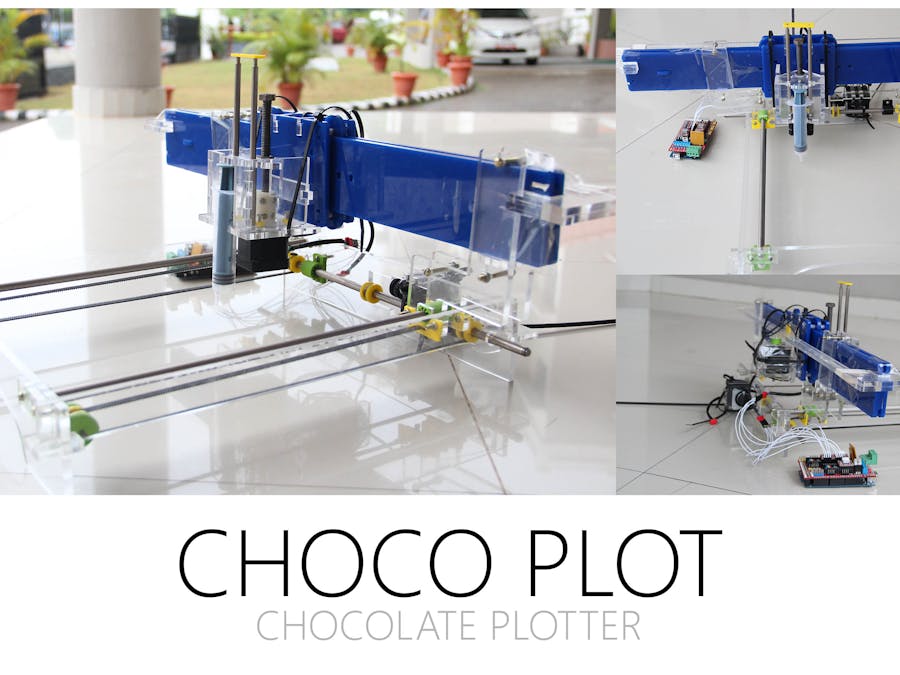
Final assembled
Problems and possible solutions
- 3D printed coupling for the gear and timing pulley deformed due to screw forces. This made them eccentric. Actually 3d printed coupling itself are not perfectly cylindrical. Coating the surface with quick setting glue helps. I also paused the print and I filled the inside mesh of the structure with quick setting glue, and continue print. This gave a tougher piece but, due to heat the volatile quick setting glue resive evaporates and forms a cloud of resin particles that causes burning sensation in the eyes.
- Acrylic breaks easily and is brittle. To reduce breakage use rounded corners to avoid stress concentration. They also dont take torque well.
Used Arduino mega with RAMPS motor shield and Marlin firmware. Pronterface was used as the gcode sending software. The following changes had to be made in the marlin firmware in order for it to work smoothly with our setup.
Config.h
Baudrate is 250000 by default, pronterface had problems with 250000
Disabling temperatre sensor.
Disabling limit switches, since currently we arent using them.
  Â
Wanted it to move in negative direction too, its convenient for testing purpose same is true for minimum position and max position.
SanityCheck.h
        Â
Commenting out the last condition was necessary, because it doesnt compile with temperature sesor 0 disabled and throws error at compilation.
Kinematics and calibration runs.The x steps per mm was found by running the pinion one full rotation and measuring the distance moved by the axis during this move and 3200 (steps for full rotation) by this distance gives steps per mm. To measure the steps per mm of the extruder I set the extruder steps permm to as that of x axis and just extruded it while running the x axis as the multiples of moves of x axis, until I found a satisfactory thickness of the extrusion over the move, of course the distance of the nozzle from the work surface should also be maintained the same. This multiple will be multiplied by x steps per mm to arrve at the extruder steps per mm.
Steps per mm 32 is used initially because its convenient that for a move of 100 through g code or saftware the motor make one full rotation. The moves of 10mm 1mm or 100mm are stadard moves in the software inteface.
The axis moved 59 mm for full rotation. Steps per mm of x axis was found as 3200/59 = 54.2372.The extrution of twice the length of x move seemed to give good extrusion results hence the steps per mm of extruder was put as twice that of the measured stepss per mm of x axis. This was meant for testing only. Need to update this in slicing setting too.
Problems and possible solutions
- 3D printed couplings of the motor in extruder slipping from the shaft due to pulling force while compressing the syringe.It would have been very helpful if the shaft had a part flat section to enable griping of pulleys. 3D printed parts cant take a heavy load uneless itelligently modified.


Comments