


Software apps and online services | ||||||
 |
| |||||
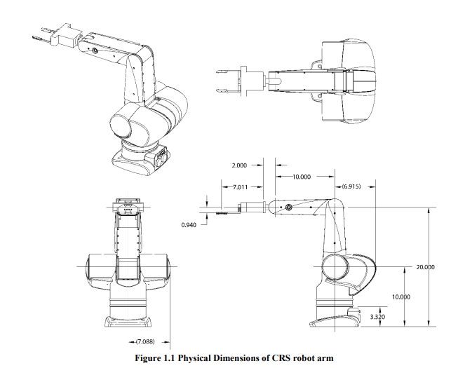
The objective of this project is to utilize a task-space force controller to control a CRS robot arm along a path characterized by several user-defined waypoints. On the last waypoint, the robot arm was programmed to exert a constant force upon a specified object. By generating the desired path from the pre-defined waypoints and calculating the end-effector location from the inverse kinematics equations, a robust task-space control algorithm was developed in the C language to control the motor torque for each joint. A task-space controller was used because all the waypoints are measured in the global coordinate system (task space). To exert a constant force, a force controller is added. Information regarding controllers will be discussed in later sections. The configuration used in this project is shown
The CRS robot arm is a 3-link robot that has 3 revolute joints. Similar to most robot arms, this CRS robot arm has a peg-shaped end-effector attached at the end of the last link. The motors that are used to actuate these joints are controlled by a TMS320F28335 DSP controller. The TMS320F28335 DSP controller is a high-performance digital signal processor that is developed by Texas Instruments. It is being widely used on many control applications such as mobile robots and robotic arms.
The demonstration run of this project consists of a series of straight line movements to move the end-effector to its desired locations and complete the tasks. There are several key steps for the robot arm to complete the demonstration run:
Move the robot arm from its resting position to a predefined location (waypoint1 to waypoint2).
Move the robot’s peg right above a hole on the left of the robot arm using several straight line trajectories (waypoint2 to waypoint 3).
Insert the peg into the hole and stay for at least 0.5 seconds while keeping the peg at a required depth marked by a line on the peg. Then pull the peg out of the hole (waypoint4).
Move to the entrance of a zig-zag pattern on the robot’s left while avoiding obstacles on the way using a number of straight line trajectories (waypoint4 to waypoint5).
Let the peg navigate through the zig-zag pattern while keeping a required depth in the pattern marked by another line on the peg (waypoints 5, 6, and 7).
Move the peg right above the egg after exiting the zig-zag pattern using a number of straight line trajectories (waypoint 7 to waypoint 8).
Press the egg with the peg so the scale reads between 500 and 1000 grams without breaking the egg, this force should last for at least 2 seconds (waypoint 9).
Return the robot arm to its “zero” position, that is all joint angles are zero and the end-effector has (x, y, z) coordinates (0.254, 0, 0.508) in meters (waypoint 9 to waypoint 10).
Notice that some steps between waypoints require several straight line trajectories to complete, such as the movement from the resting position to the pose above the hole. Additional waypoints are also required to avoid obstacles when moving the robot arm from above the hole to the entrance of the zig-zag and navigating through the zig-zag. There are 23 coordinates in total that constructed the series of straight line trajectories of this demonstration run.
In this project, an impedance controller is used for all waypoints except for the last one, where a force controller is utilized. The impedance controller regulates the interaction between the robot arm and its environment by controlling the stiffness, damping, and impedance of the robot arm. It is useful for situations where the robot arm needs to make contact with an object and maintain a certain level of compliance for example the zig-pag. It allows the robot arm to be more flexible and versatile in handling various tasks.
On the other hand, a force controller is used for the last waypoint where the robot arm is required to exert a constant force on the specified object. The force controller regulates the force applied by the end-effector of the robot arm. It is useful for applications where the robot arm needs to apply a precise amount of force or maintain a certain level of force over time.
However, both controllers have their own limitations. Using an impedance requires a thorough understanding of the environment and the robot arm's behavior to achieve optimal performance. The kp and kd value need to be changed in different situation to realse the robot arm in differen orientation. The force controller won’t be able to handle the uncertainties, they need to be designed precisely.
Overall, the choice of controller depends on the specific application and the task requirements. In this project, the impedance controller is used for most of the waypoints to provide flexibility and adaptability, while the force controller is used for the last waypoint to achieve a precise and consistent force.
The demo video is shown in below link


Comments