

Hardware components | ||||||
 |
| × | 1 | |||
| × | 1 | ||||
 |
| × | 1 | |||
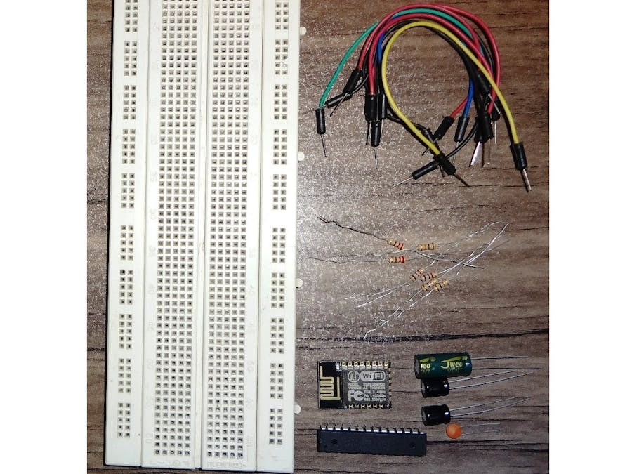
WiCard is an OTA programmable WiFi module. Like “Arduino," you can make your own WiCard on a breadboard. If you want to make WiCard on a breadboard before making the PCB, all you need is some resistors and capacitors, a breadboard, wires, an ATmega8A (DIP), and an ESP8266 module (with a 32 Megabit flash memory).
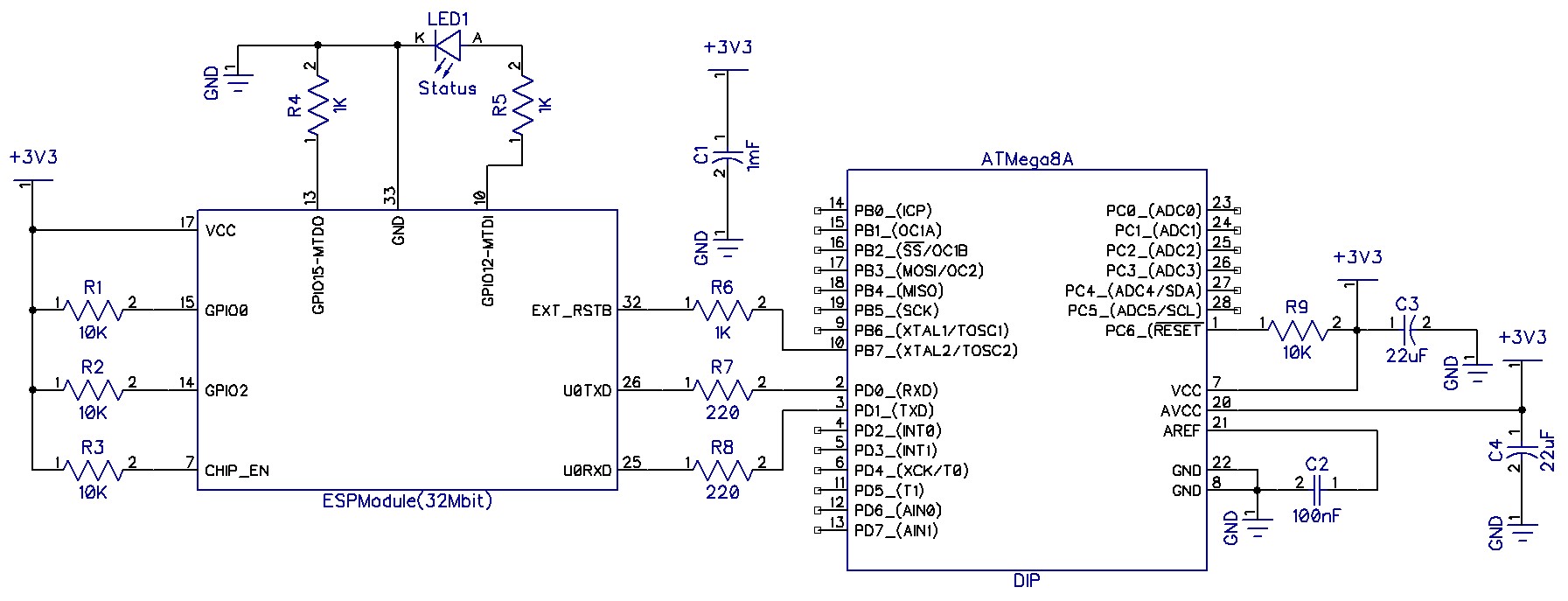
The SchematicHere’s the connections guide:
First of all, you have to program the ATmega8A with an AVR parallel programmer (high voltage programmer). Furthermore if you’re going to use a SPI programmer, you must put a pull up resistor for PC6 (Reset pin) of ATmega8A. (Download the ATmega8A flash file)
So the fuse byte in AVR parallel programming, set the “Fuse High Byte” to 0x78, the “Fuse Low Byte” to 0xA4, and the “Lock Bits Byte” to 0xFC.
The fuse byte in AVR SPI programming, set the “Fuse High Byte” to 0xD8, the “Fuse Low Byte” to 0xA4, and the “Lock Bits Byte” to 0xFC.
Then program the ESP8266 module with flash download tool and a USB to serial adapter. Due to firmware files addresses, the esp module must have a 32MBit flash memory. So if your module has not a 32Mbit Flash, try to replace its flash memory with a 32Mbit. For example W25Q32. (Download ESP Module firmware files)
The firmware for ESP8266EX includes 6 files:
- ESP8266EX_0x000000: Must be copied at address 0x0 in the 32Mbit flash memory. This file includes some initial system settings.
- ESP8266EX_0x001000: Must be copied at address 0x1000 in the 32Mbit flash memory. This file includes the firmware program data.
- ESP8266EX_0x0FE000: Must be copied at address 0xfe000 in the 32Mbit flash memory. This is a 4KB blank file for the system settings.
- ESP8266EX_0x300000: should be copied at address 0x300000 in the 32Mbit flash memory. This file includes internal webpage data.
- ESP8266EX_0x3FC000: should be copied at address 0x3fc000 in the 32Mbit flash memory. This file includes some initial wireless/WiFi settings.
- ESP8266EX_0x3FE000: should be copied at address 0x3fe000 in the 32Mbit flash memory. This is a blank file for the system settings.
Here's ESP Flash Tool settings:
Finally assemble the module after programming the firmware on ATMaga8A and ESP module (I’m using an ESP12 module which I have replaced its flash with a W25Q32).
The following table will help you to find the WiCard port pins:
Also you can use GPIO 12 (MTDI) of your ESP8266 module (if it’s available) as “NET Status LED”. Besides that, you can use GPIO 14 (MTMS) as “Program Status LED” and GPIO 15 (MTCK) as “Error LED”.
To finding out another stuff about WiCard WiFi Module, please refer to our website and blog.


Comments