


Hardware components | ||||||
 |
| × | 1 | |||
| × | 2 | ||||
 |
| × | 2 | |||
| × | 1 | ||||
| × | 1 | ||||
 |
| × | 1 | |||
| × | 1 | ||||
| × | 1 | ||||
 |
| × | 1 | |||
| × | 1 | ||||
Hand tools and fabrication machines | ||||||
 |
| |||||
 |
| |||||
Since my childhood, I've loved Star Wars. I've always wanted to have a replica lightsaber that I could have duels with, but the high quality ones with diverse functionality are hundreds of dollars. Seeing the opportunity this course presented with learning basic electronics, my friend Liam and I had an idea for a project: we could build our own lightsabers and customize them however we wanted. Not only would we be saving money, we could proudly duel with lightsabers that we completely built ourselves.
As Liam and I are both non-engineering majors with limited experience in electrical engineering and programming, we split the project's tasks. I would focus on implementing the buttons and encoding the LED light strips, and he would work on the IMU motion sensor and sound system. Together, we will implement our projects to each have fully functioning lightsabers. This page describes my process of integrating the button control and lights.
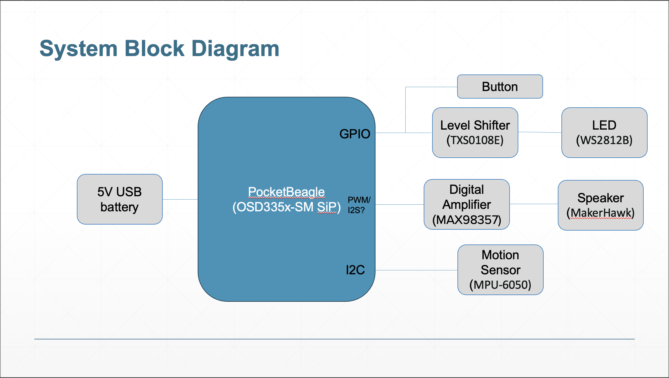
Build InstructionsWhile the programming tasks were split up, both Liam and I implemented all the hardware for the fully functioning lightsaber. Below are the parts necessary for the project and how they were implemented together on the breadboard.
PocketBeagle
For this project, we used PocketBeagle as the computer. Erik Welsh provided all components used for the project, and our PocketBeagles already had pre-soldered pins and were attached to a breadboard. All components will be connected to the PocketBeagle for power and software implementation.
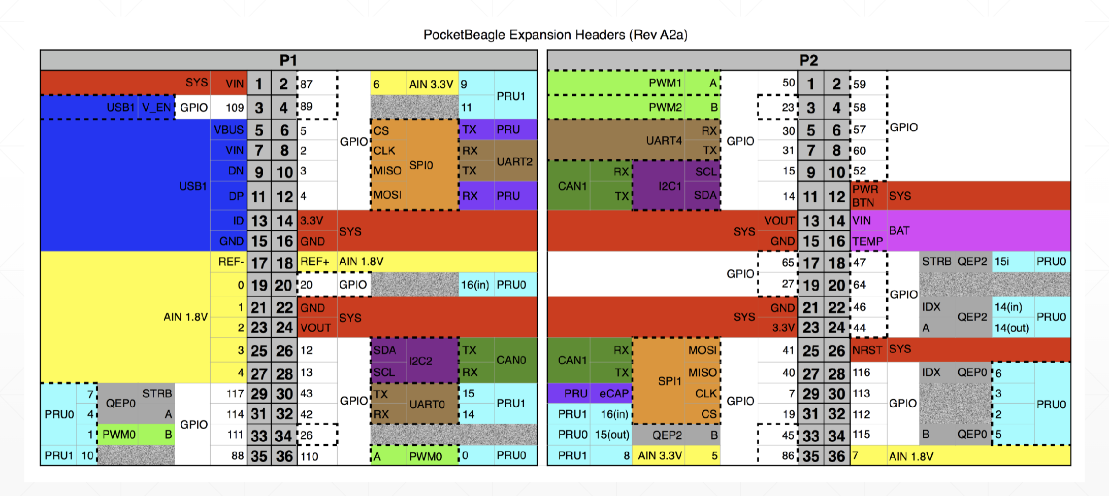
- Pin P1_14 is 3.3V and is connected to the left rail's (+) lane
- Pin P1_16 is GND and is connected to the left rail's (-) lane
Battery
To power the project independently, a 5V external battery pack was used. Initially, the plan was to power the entire PocketBeagle through this source. However, I ran into issues with power when working with the device plugged into my laptop's USB-A to USB-C adaptor: the adaptor was drawing too much power for the 5V components (LED light strips), and this caused the PocketBeagles to break completely. To avoid this issue, the 5V battery pack powered the LED lights independently, and the 5V power can be routed separately to the PocketBeagle and 3.3V output rather than through the microUSB connection. Currently, the battery is set up as seen in the image below, where pins from the battery attach to the right rail on the breadboard that I designated for 5V. In the future, power from this rail will be routed to the 3.3V pins on the PocketBeagle to supply power to the rest of the components when the device is used independently.
Buttons
Currently, two buttons are implemented into the system. These are used to control functions of the lightsaber like turning on the blade and changing colors. One end of the button is connected with a 1kΩ to 3.3V power and a GPIO pin, and the other is connected to ground. The pins used are:
- P2_02 configured as GPIO (brown wire)
- P2_04 configured as GPIO (brown wire)
LevelShifter
This device is used to connect devices requiring different power levels to work together without causing damage. This component was provided pre-soldered. The level shifter is placed across the center of the board, with side A on the 3.3V side of the board and side B on the 5V side.
- Connect VA to 3.3V
- Connect VB to 5V
- Connect all grounds to GND
- Though it is hard to see in the picture, connect OE to VA using a wire
- Connect A1 to P1_08 configured as GPIO
LEDLightStrip
The LED strips are used to power the blade. They will ignite in the fashion of a proper lightsaber, from the hilt to the tip of the blade, and vice versa for deactivation. These LEDs will also change color, allowing customization. The final goal is for these lights to flicker, allowing more dynamics, and flash when the lightsaber makes contact with another.
Connect the LED strip pins to the level shifter as follows:
- Connect +5V to VB (blue wire)
- Connect (-) to GND (white wire)
- Connect Din to B1 (purple wire)
IMU
The IMU is a motion sensor that will detect movement and rotation of the lightsaber. Acceleration and impact can be calculated using the data taken from this device to drive light and sound-effects of the lightsaber.
This component is powered using 3.3V. Soldering was required to implement this component to the breadboard. Note the following to set it up:
- Connect VCC to 3.3V power
- Connect GND to ground
- Connect SCL to P1_26 as I2C (orange wire)
- Connect SDA to P1_28 as I2C (red wire)
Digital Amplifier and Speaker
The digital amplifier is an I2S device that will drive the speakers to provide our lightsaber with high quality sound. Soldering was required to implement this component to the breadboard. See below for the proper connections:
- Connect Vin to 5V power
- Connect GND to ground
- Connect Din to P2_31 (brown wire)
- Connect BCLK to P1_36 (green wire)
- Connect LRC to P1_33 (yellow wire)
- Connect the speaker's + and - terminals to the corresponding + and - terminals on the digital amplifier (see red and orange wires)
Currently, only the hardware is set up. As the digital amplifier is I2S, we have had trouble trying to integrate the functionality with the PocketBeagle. However, once these software issues are resolved, we can implement this component to the lightsaber's functionality.
Final Product
Below is what the final product looks like. All hardware needed for the complete lightsaber design is fully integrated.
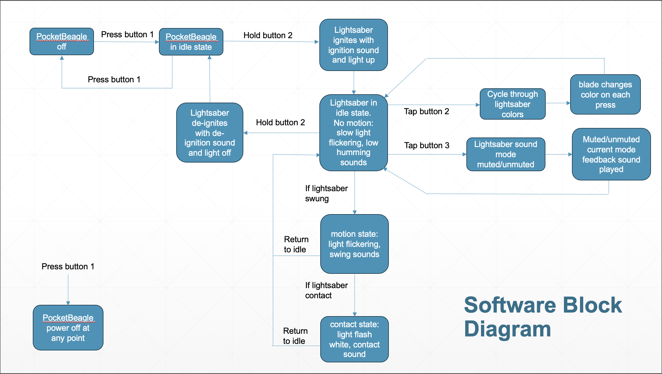
To use the lightsaber, pressing the button will ignite the blade, causing the LED light strip to turn on from the hilt to the tip of the blade. While the blade is on, single button presses will change the color of the LEDs, cycling through a select preset color list. To deactivate the blade, simply press and hold the button, and the LEDs will retract from the blade down toward the hilt. When re-ignited, the blade remains the same color as it was when deactivated. See a video below for a demonstration.
Next StepsCurrently, the button and light functionality works pretty seamlessly. However, there can be some issues with the button timing, as you may notice in the video demonstration. When the blade was activated for the second time, the color also switched immediately to the next in the cycle, even without another button press. These issues will be debugged for more consistent function in the future. Additionally, the LEDs are static. I wish to introduce small, constant, random changes in the RGB values while the LEDs are on to give the lightsaber a more realistic feel as if it were humming with energy.
Liam currently has functionality of the IMU in detecting blade swings and contact through acceleration calculations. However, the speaker is currently non-functional. Once the speaker software becomes implemented, we can begin to implement all of the lightsaber systems together to create the final product.
The final features would include all systems working simultaneously during use. While the blade is ignited, the LEDs would flicker gently, and a low humming sound would be emitted from the speakers. When swung, the speakers would play a more dynamic lightsaber swinging sound. Upon contact with another lightsaber or object, the lights would flash white on the impact, and the speaker would play a lightsaber impact sound. Additionally, a second button will be used to mute/unmute and control the volume of the speakers. Power connections will be better tuned to run the device independently on its own power source, and the device will boot and run the lightsaber program automatically.
After all the hardware and software is fully functioning, we will design customized 3-D printed hilts to house the device and use a polycarbonate tube as the blade of the saber.


_3u05Tpwasz.png?auto=compress%2Cformat&w=40&h=40&fit=fillmax&bg=fff&dpr=2)

Comments