I grow vegetables in a community garden two miles from my house, so when I was given the opportunity to test a cellular data system for makers and hackers, my first thought was to use it for the garden to monitor soil moisture. Sometimes I’m not able to get out there for several days at a time, so some sort of warning that the garden needed water would be really helpful. Since the garden has no power or internet available, a self-contained device with its own internet connection is just the ticket!
Hologram.io provides a cellular data service that works with any device that accepts a SIM card, but they also have a programmable board called the Dash with some great features for this project: small, built-in Li-Ion battery compatibility and charging, built-in cellular modem, and programs right in the Arduino IDE. This allowed me to build the project with minimum size and number of pieces.
Besides an off-site garden, this system would be great for orchards, greenhouses, or just regular plants on large properties.
This project from a very high level:
- Read a sensor using a self-contained, battery-powered microcontroller
- Send data via cellular to the Hologram cloud service which manages the device
- Pass data to the Losant cloud service for visualization
To get started, I registered my new SIM card on the Hologram dashboard and followed their tutorial to get the Dash board up and running. As part of the process I could see debug commands from the modem which included messages about which cell carrier it was connecting to—sometimes it was AT&T, and sometimes T-Mobile, so it was good to know that the Hologram system had the flexibility to get me the best signal available. It’s also convenient that the service cost to keep a SIM card active is so low and it can be paused at any time.
The code was fairly simple:
Startup:
- Load the Dash library, start the cloud service, and send an initial message
Main loop:
- “Snooze” the Dash for 1 minute to allow the modem to connect
- Read the moisture sensor and send data to the cloud
- “Deep sleep” for 1 hour (or whatever reporting interval is good for the garden)
The snooze
and deepSleep
functions are unique to the Dash for saving power, part of the Dash class. Snooze
is like a low-power version of the standard Arduino delay
, and deepSleep
is a very low power mode that is only woken up by a timer (like I used) or with a hardware interrupt.
It’s also worth noting a trick I used for the moisture sensor to avoid corrosion. If the power to the sensor were applied continuously and there was always current flowing between the two electrodes through the dirt, eventually the electrodes would corrode. By only powering the sensor while taking the measurement, we can dramatically extend its life. This is accomplished by hooking up the Vcc of the sensor to a digital output pin on the Dash. By turning that pin HI, it powers the sensor, the signal can be read, and then the digital power pin can go back LO. This way, the sensor is only powered 0.1 seconds out of every hour, which also saves battery life.
That takes care of reading the sensor and sending the data to the Hologram cloud. Once it’s there, it needs to be processed in some useful way. A free cloud service that can help with this is called Losant, and to set it up for a relatively "simple" project like this I followed the instructions from this "Unicorn Finder" tutorial which included sending GPS data from a Hologram SIM card to the Losant cloud via the Hologram cloud.
That tutorial will show you the actual tactics to implement the system in Losant, but here I’ll explain the strategy of how it all works to get some fundamental understanding:
- The Dash will read the sensor and send a message to the Hologram cloud. We have to format the message sent from the Dash like a JSON to include the variables we want to send, in this case moisture and battery voltage. We want that message to look like this:
{"moisture": 152, "battery_level": 80}
- The Hologram “routes” look at all the messages coming into the cloud and activate if they include the “channels” that the route subscribes to. If they do, they send the data to the specified URL, which in this case will be the webhook that is set up in the Losant cloud to receive the data.
- The webhook activates the Losant “workflow” and passes your data long. Here we set up the webhook block to alter a “device state”.
- The Device State block has to parse the incoming data into the variables we have defined for the device (
moistureandbattery_level) by setting the state value to look like this:{{data.body.moisture}}
- Now the device states will be updated, which will allow the Losant “dashboard” to update your indicators and plots! Note that depending on the “time range” and “one point every…” settings in the dashboard, the plots may not update immediately.
Notes on debugging the cloud communication:
- Using the Losant debug feature in the workflow is critical here! It lets you see the data that has come in so that you can adjust your Dash code to format it nicely for a JSON and then format your device state value to properly read the JSON.
- However, the Losant webhook debugger will not even register a request if it includes text in an invalid JSON format, so try just sending a blank message from the Dash or formatting your message on the Dash like a JSON right away.
- Whatever you send from the dash will be enclosed with
{"body":and}. Then Losant will enclose that with{"data":and}. Hence, to access our values, we use thedata.body.variablepath like above.
- Look in my code to see exactly how I built the JSON -- the section is marked.
- If needed, Postman is a service to let you manually trigger the Losant webhook to help debug.
- From the opposite direction, RequestBin is a service that lets you see what is actually coming out of the Hologram cloud service, also helpful in debugging.
- Phew.
To build the finished product, I wanted it to be waterproof, battery operated, and unobtrusive. Finding a sealed project box was easy enough, but how would I incorporate the soil moisture sensor which was little more than a bare PCB? I considered having the sensor live inside the project box with the legs sticking out, but didn’t like the idea of the box flopping over or covering the soil that I was trying to measure the moisture of.
I decided to make the sensor separate and attached via an umbilical (really just the three wires). Potting the entire sensor board in Sugru protects it from damage and the elements, and also allows the feedthrough into the project box to be sealed. Electrical tape can protect the sensor wires.
I followed these steps for the hardware construction:
- Drill a hole in the project box where the sensor wires will feed through
- Tape up the two sets of three wires (female-female wires attach to the sensor, and male-male wires attach to the solderless breadboard). The male end should be taped enough so that a portion goes through the feedthrough, but then stops so that the wires can be connected to the right places on the breadboard.
- (I left the male-female connection ends of the wires unwrapped so that the whole sensor unit could be replaced if needed without undoing all the wrap.)
- Pot the entire moisture sensor in Sugru, including the connected wires up past the start of the electrical tape. Sugru is amazing tool for makers: a hand-formable rubber that sticks to most surfaces and cures in 24 hours. Here it’s perfect for providing waterproofing and structure simultaneously. I used two packs of Sugru, one black and one white, mixed together to make gray.
- One fifth or so of the two packs was used to seal the feedthrough into the project box, again covering the electrical tape on the wires. Now it provides structure, waterproofing, and stress relief.
- Tip: a zip tie around the wires on the inside of the box can further protect them from being pulled out.
- Connect the new sensor pigtail to the other bundle and seal with electrical tape.
- Now we can fill up the project box!
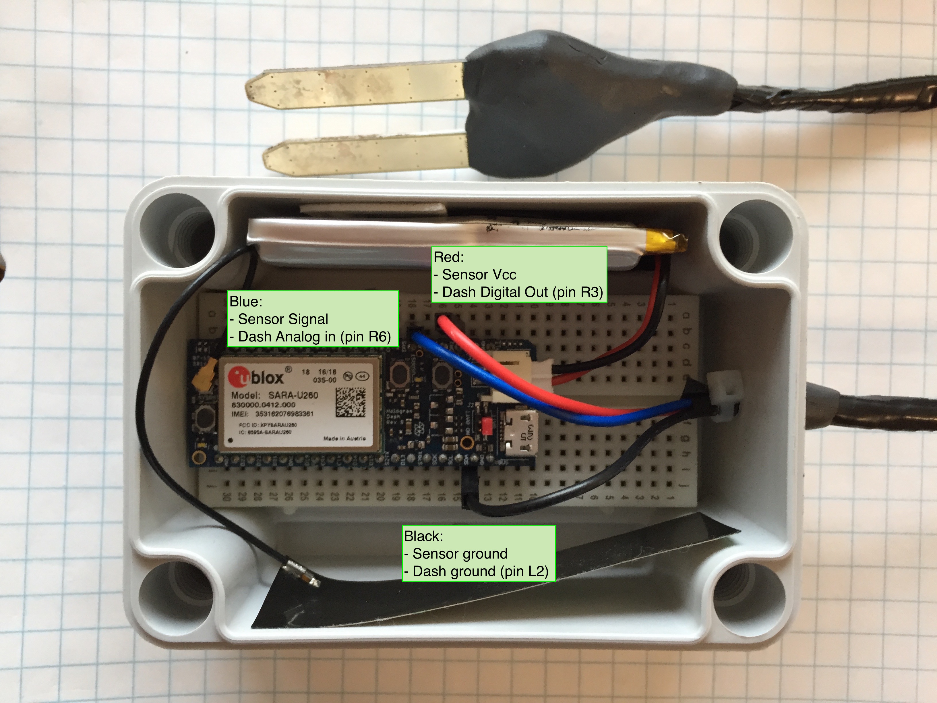
- I fit a solderless breadboard inside by removing the power rails. The built-in double-sided tape keeps it stuck to the bottom.
- For a future build, I would consider installing the board so that the micro USB port is tilted up slightly to make a cable easier to connect.
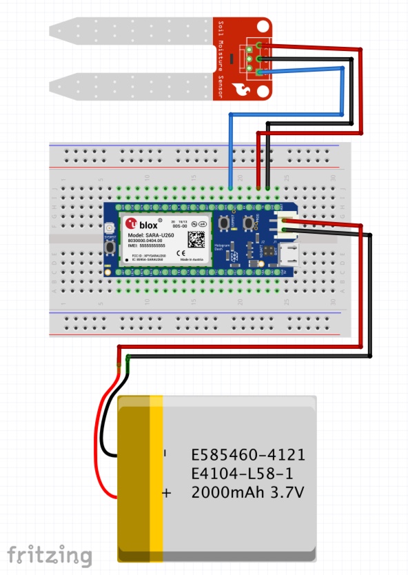
- The sensor connects to the dash via an analog input (sensor signal), digital output (sensor power), and ground pins. Pinout reference page.
- The rechargeable battery can tuck into one side of the case and stick there with some extra double-sided tape from the breadboard power rails.
- The cellular antenna can tuck into the other side -- I only used ~¼” of the built-in adhesive just in case I needed to move it, and it keeps the antenna straighter (some bending is fine, but probably not creasing).
I tested the sensor by having it output the moisture content signal to the serial monitor on my computer at 0.5Hz. Holding it between my fingers, placing in water, and placing in different types of dirt all gave different readings from zero (open air) to 1023 (in a glass of water). This makes sense with the sensor using the full voltage range of ground to Vcc. The ADC of the Dash is 10-bit by default so it ought to read from 0-1023.
For my garden, damp soil read 200-250, and very dry soil read 30-60. This would have to be calibrated for the specific soil types in your garden, which is easy enough to do: what does it read after watering or raining, and what does it read when you would want to water it?
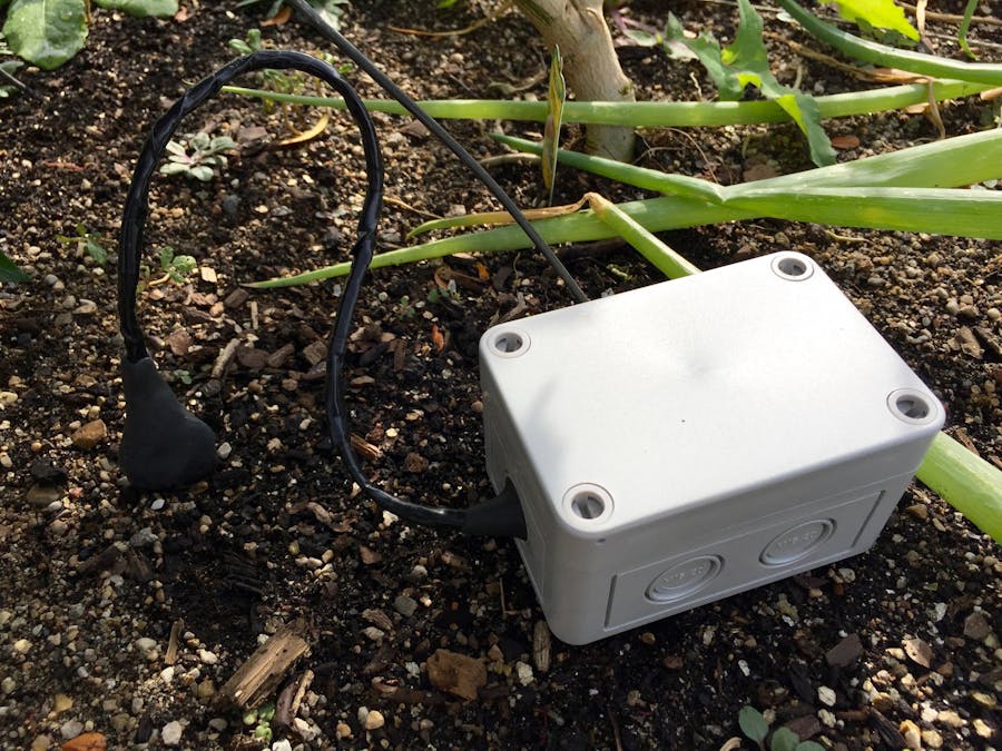
Here is the finished product installed in my garden in all its glory. I can leave it here for several days at a time before it needs a charge. No reason a larger battery couldn’t be used in this project, and slowing down the reporting frequency will further increase battery life. A great expansion of this project would be to add solar power! You could also add email/text alerts in the Losant cloud at certain sensor thresholds. Next time I would also build in a USB charging cable to make battery charging easier.
This system will be super useful next season, or even on some indoor potted plants over the winter. Ultimately I ended up with a nice weatherproof device that should last a long time outdoors, and I even made two cloud services talk to each other, opening a world of possibilities for future projects.
This project can be adapted for pretty much any remote sensing application. What are you building? How would you improve the system?
Enjoy!
-Mike
You can read more about me and my projects on my blog, including additional photos of this project.
(This project was made as part of Hologram's Hacker-In-Residence program. For more information, contact Sheena, Hologram's content coordinator, at sheena@hologram.io)


_3u05Tpwasz.png?auto=compress%2Cformat&w=40&h=40&fit=fillmax&bg=fff&dpr=2)
Comments