


Hardware components | ||||||
| × | 1 | ||||
| × | 1 | ||||
 |
| × | 1 | |||
| × | 1 | ||||
| × | 2 | ||||
| × | 1 | ||||
| × | 1 | ||||
| × | 1 | ||||
Software apps and online services | ||||||
 |
| |||||
Hand tools and fabrication machines | ||||||
 |
| |||||
| ||||||
Don't we all love how this whole MCU business is playing out, with those GPIOs, providing us with super-powers - the word alone - "GPIO" - sends shivers of joy down the spine of every maker. But wait - it's just 3.3 volts.
Yeah no problem, just add a logic level shifter from 3.3 to 5V, then try to run your motor driver board with 5 Volt signals to power 12 Volt motors, it might work. I actually did that, controlling 12V 1 Amp Steppers via Darlington NPN transistors, back then connecting the 5 Volts of the printer port over a protection diode and a resistor directly to the base of the transistor - it worked. Later I slapped together an 8 channel 3.3V to 5V logic level shifter, with 2 MOSFETS per channel, so I could use my 5V "Driver" board on a Raspberry Pi Zero - it worked too. But frankly the whole thing became as big as a shoebox, and I felt it was clumsy and over-complicated.
If there were only a simple solution, to drive any load with minimal fuss and investment, from a 3.3 volt GPIO. So I sat down and re-imagined the whole scenario. After some tinkering in simulation and successful practical tests I finally came up with a working design that I am actually even a bit proud of so that I want to share it with you guys, here and now.
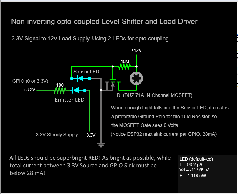
First, to see how simple it is, the BOM (for 1 channel):- 2 LEDs (red clear dome, super-bright, 20 to 100 mA)
- 1 Resistor 100 ohm
- 1 Resistor 10 Megaohm
- 1 N-Channel MOSFET (I used BUZ 71A, but other N-MOSFETs may work just as well. Simple NPN transistors won't work.)
And that's it. These few components will provide us with the following functionalities:
- Non-inverting Logic Level-shifter (1-directional) from 3.3v to 12 volt or any other wanted voltage (maybe below 24V?)
- Opto-Coupler for full MCU protection
- Unlimited current control for bigger loads (still limited by the MOSFET, naturally)
Notice my choice to implement also Opto-Coupling was rather because it made the whole level shifting simpler, than it was to protect the MCU, but of course additional protection is welcome.
To use this circuit, you will also need: an MCU that has 3.3v GPIOs, a powersupply to power the load, eg. 12V Laptop supply, a powersupply for the MCU, some wires and soldering and/or PCBing equipment, and finally a test load, such as a 12 V DC motor. Of cource you can also use some other output voltage, like a 9V motor and supply. Or run a 12 V motor with 6 V at low power. Whatever you fancy.
Now, when you look at my schematic you may think I am a fool who put the LEDs the wrong way into the circuit - nothing could be further from the facts. Few people know that an LED can be used as a Light sensor - when light shines into an LED then it produces a tiny reverse current. That means you will read about 20 to 40 millivolts at the positive terminal (meaning, where it normally would sink the positive supply, it now wants to source its generated current).
What happens in this circuit therefor is: with no light falling into the sensor LED it will be just a blocking diode, and the 12 volts that are coming from the 10 Mega-Ohm resistor will ignore this path, and hence go to the MOSFET Gate and fully unblock the connection from Drain to Source, so the motor gets full power because now the current can flow to ground.
On the other hand, if enough light falls into the sensor, it will generate a reverse current with about -40 millivolts - not much, but enough to make this LED look like Ground to the 10 MOhm resistor, hence the tiny current from the latter now prefers to flow through the LED right into ground, and therefor the Gate of the MOSFET sees zero volts, causing it to block the flow from Drain to Source completely.
Notice the sensor is working in reverse logic: when it sees no light then the motor is powered, but when light falls into it, to motor stops. We could just live with it and always make sure to power on the MCU and program first, and the motor power supply later. Handle it in software and always keep the LEDs on when motors should not move. Still, it bears the risk of motors running wild if - for some reason - the emitter LED is off when the Motor power supply is turned on. I don't like that.
To solve this in a simple way and get non-inverting logic, we can do the following:
The Emitter LED isn't powered by the GPIO, but rather does the GPIO work as a sink for it, or you could call it a dynamic pseudo-ground, all while the LED is powered by a permanent 3.3V source. This way we can still turn the LED on and off by the GPIO, but now the LED is on when we write "0" to the pin, and off when we write "1". That's because "1" is 3.3 Volt, and there cannot be any current flow between a 3.3 Volt supply and a 3.3 Volt GPIO. Yet, if the GPIO is set to "0", it is practically at zero volts, therefor the current from the 3.3 volt supply now flows through the LED into the GPIO, and the LED lighs up. Keep in mind the amount of current a GPIO can sink is limited, on ESP32 it is 28 mA at 3.3V.
While the steady 3.3 V supply for the emitter diode could be provided by the MCU itself, for the reasons explained above I would rather suggest it be provided by the 12V source (or 12V and 3.3V have a shared source that is switched instead), to make sure the emitter-LED is always on whenever the 12 V source is on.
The MOSFETs I used are BUZ 71A, sold between 70 cents and 4 bucks, tho I found a bag of 90 pcs at a garage sale for 3 bucks. The LEDs are also cheap when bought by the 100s, just like the resistors, so I'd locate this device without a PCB at probably 1 dollar per Channel.
I'm planning to use it with 4-phase steppers, because using 2-phase steppers would additionally require some kind of H-bridge, which in the version containing short-circuit-protection requires at least another 5 MOSFETS or Transistors for every motor, where 4-phase stepper motors work with positive voltage only and can be connected directly to this NIOCLLHLPU (non-inverting opto-coupled logic-level-shifting-heavy-load-powering-unit). You ain't got no NIOCLLHLPU? Everybody has a NIOCLLHLPU these days. j/k.
And that surprisingly already concludes my elaboration on the subject matter. I hope this circuit is as useful for anybody out there as it is for me. And have Merry Christmas everybody.
Little Update Dec. 28th 2025:
For one, the initially provided Code doesn't work, instead you can stay in pinMode(myGPIO, OUTPUT), and simply digitalWrite() HIGH or LOW to the pin.
But there is also a bigger issue: as long as the GPIOs are not specifically set to zero by a digitalWrite(myGPIO, LOW), they cannot sink any current, so in terms of the "risk" mentioned earlier, we are back on square one. It's kind of surprising, as I measured at least some connectivity between the GPIOs and ground, even when the MCU is completely unpowered. But despite a common Ground with the 12V source, it just wouldn't sink the current by default. If anybody is seeing what I'm doing wrong, please let me know. Other than that, the circuit works just fine in a test with a Lilygo Amoled Plus with ESP32 S3.
I should say, I have to use up a bag of superbright red LEDs that have internally 5 LED elements in parallel. As the 3.3V source I use a 5V USB supply that goes through 3 standard diodes, which lowers the voltage to about 3.2 Volt. The emitter LED then runs at about 1.72 Volts, followed by the 100 ohm resistor, resulting in total of about 12 mA - perfectly enough to switch the sensor LED. However, your LEDs may be different. I tried in simulation to use standard 20mA LEDs, they ran at about 1.82V and about 16mA (IIRC), so I guess either type of LED would work just fine. Just make sure not to sink too much current in your MCU GPIOs.
For now I will just go ahead and use the software solution mentioned above. (Essentially, turn 12V supply on after the program has set all relevant pins LOW.)
2nd little Update Jan. 3rd, 2026
In order to solve the issue described above, I made a little test using a cascade of 3 NPN-transistors in a Darlington-configuration. The goal was to create a weak 12V signal directly from a 3.3V GPIO, so that it can switch a main MOSFET that sits between all the channel MOSFETs and ground. So if this final MOSFET is not specifically unblocked by 3.3 Volts on a GPIO then none of the loads will be powered.
Theoretically we could have used the same method to implement the whole level shifting for the channels in the first place. But the initial circuit still uses less parts and probably cheaper parts while additionally providing opto-coupling.
So this main switch circuit would then be fairly simple: a protective diode at a GPIO, so no current may flow in (in case of any back-EMF-spikes from inductive loads), followed by a resistor, 170 Ohm worked here. Then this signal goes to the base of NPN-transistor 1. The emitter of the transistor 1 goes to the base of transistor 2, and the emitter of transistor 2 goes to the base of transistor 3. The emitter of transistor 3 finally goes to the gate of the N-Channel MOSFET. All collectors of the 3 transistors are connected over a reasonable resistor (1k) to the 12V rail. The MOSFET at the end of this cascade has its drain pin connected to all the source pins of the channel MOSFETS, and it has its Source going directly to ground. Notice for common ground connection with the MCU you have to connect MCU ground at the source side of this final main MOSFET (where it actually directly connects to ground of the 12 supply).
As I said this is for beginners, let me just provide some transistor basics:
The N-Channel MOSFET has a gate pin which regulates the current flow through the part, based on the voltage it sees. It barely requires any current to switch the part, but it needs a voltage (contrary to NPN-transistors that are amplifying the current they get at their base pin). The actual power we want to regulate in a MOSFET then (counter-intuitively) flows from drain pin to source pin, so source is connected to ground.
The difference between NPN and PNP is, PNP expects a path from base pin to ground, and based on the amount of current this path lets pass through, the PNP transistor will let current flow from collector to emitter.
The NPN is different in that its base pin needs a certain positive current to let current flow from collector to emitter. Ideally base and collector have the same voltage, but current is actually more important, so that you can switch 12 Volts with a 5 Volt signal, although a protecting diode, preventing any current from flowing from 12V to the base and back to connected parts should be added. Common NPN transistors do amplify the current given at the base about 30 times, so their "gain" is about 30. Hence a 3-stage darlington layout provides 30x30x30 gain, about 27'000x amplification - most likely enough to exhaust your power supply and/or fry the transistors, so don't forget to add a limiting resistor in such a circuit.
Important: any inductive loads such as motors and coils must be located before any N-Channel MOSFET or NPN transistor, and the latter must then connect directly to ground. If you try it the other way around (12V+, transistor, motor, ground) it won't work. For PNP-type transistors and P-Channel-MOSFETs it is the exact opposite, but here you gotta trust me on that one: 12V+, - motor - MOSFET - Ground.
Update 3, January 6th 2026
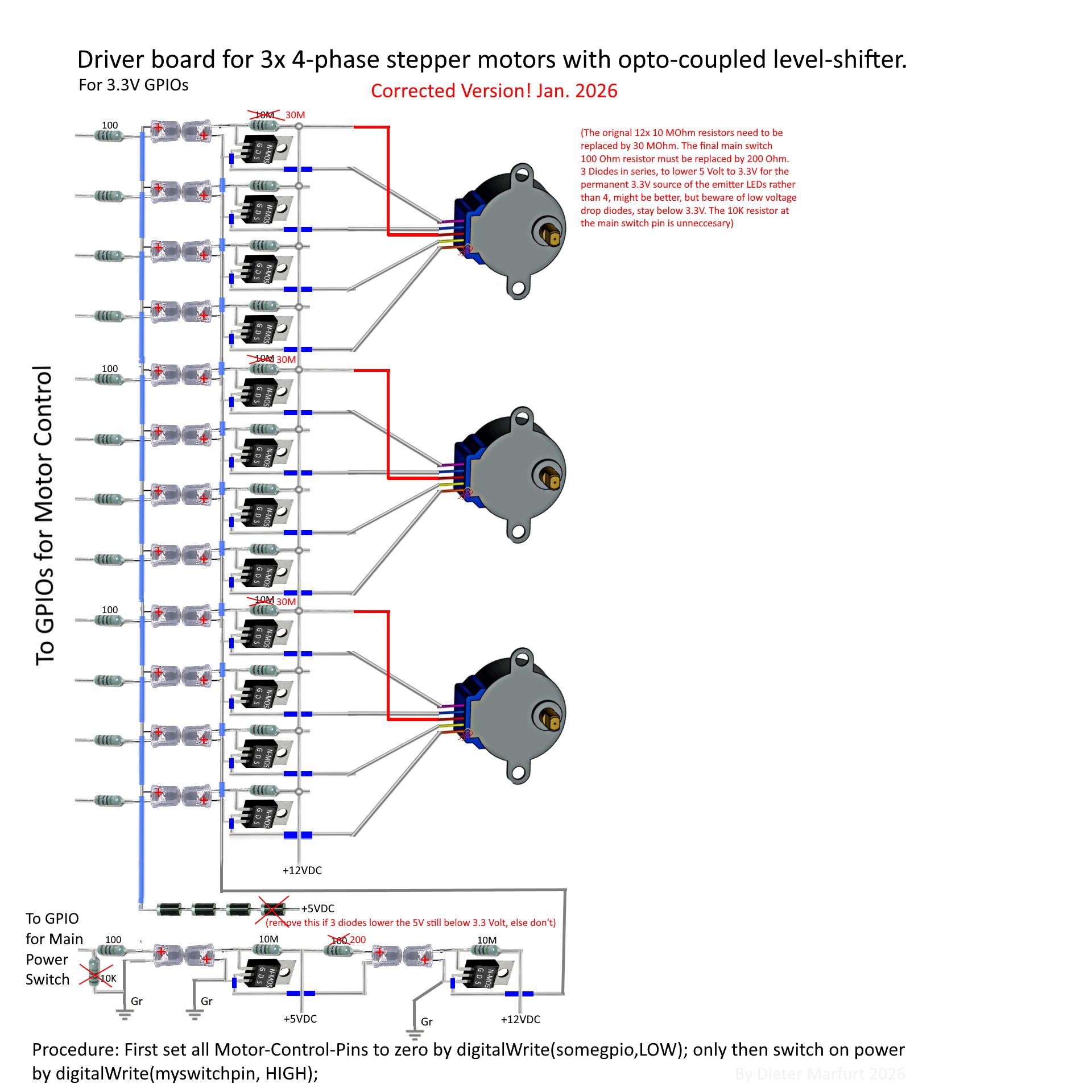
Hopefully this is the last update. Based on the solution outlined in the previous Update 2, which was an additional main switch based an a Darlington cascade, I made a schematic (see attachments section below) for a driver-board that controls 3 stepper motors. However I chose not to use the Darlington method explained earlier, but to add yet another opto-coupler, this time internally a double-coupler. Now everything is truly isolated, except for the common ground, which is ok. Also, the main switch section has a 10k pulldown resistor between GPIO and ground, so even when the MCU is unpowered, or booting (or crashing and rebooting), the motors should now stay calm.
Few things you should consider:
My mosfets already contain internal reverse diodes that allow back-EMF-spikes that may appear with inductive loads such as motors, to flow back in a civilized manner, rather than to fry any components like when there were no diode. Watch the datasheet of your mosfet, and see whether you should add diodes from source to drain.
The steady 3.3V source for the emitter LEDs is taken from a 5V USB supply, or ATX supply 5V-out. It goes then through 4 diodes which should lower the voltage to slightly under 3.3V. However different diodes have different voltage drops. Make sure to test this carefully before attaching it to your MCU: Hook up to the 5V pin of any 5V USB power supply 4 diodes in series, followed by an LED and a 100 ohm resistor that goes to ground of the USB power source. Measure the voltage from after the last diode to ground. It may be slightly less than 3.3V, but not more(!). Reduce or increase the number of diodes accordingly. Only then use it at a GPIO.
Generally, whenever there is an LED that is not a sensor, but meant to emit light, it should run at / drop about 1.7 to 1.9 Volts at about 16 mA. If these numbers are much higher, try different resistors.
Steppermotors with 4 phases have one power input and 4 power outputs. We control only the outputs. By allowing a burst of power to subsequently flow through each output in a specific order repeatedly, we turn the rotor continuously.
To find out which one of the 5 pins is the input pin, measure the resistance between all motor pins. The one pin that has the same resistance to all other 4 pins is the input pin. Keep in mind the pin-out of your motor may be different from the schematic, and besides the image depicts a common model of a 5 Volt motor, which of course should not be used with 12V power.
Tiny addendum to last Update
While I am building the driver board now and everything works fine, only the 100 ohm resistor on the schematic's bottom right side (the last resistor, that is part of the main switch section) is too low and must be 200 ohm instead. (else that LED is unnecessarily bright and may have a lowered life expectancy). Also, I use 3 diodes in series for the emitter LEDs 3.3 Volt supply from a 5 Volt source. It may work with 4 diodes too, but they are fairly dim. I actually soldered in 4 diodes, with an option to skip one of them using a wire bridge. As this project is nearing completion while I am also finally finishing my "what's at hand" CNC router, I'll keep you updated.
Addendum to the addendum
I am currently testing the stepper motor driver board IRL. Here are a few findings and correction to the schematic below. Please also consider the before-mentioned 200 ohm resistor change. Well, even tho the 10 megaohm resistor worked in a test with a 1-channel unit to turn on and off a DC motor, when trying it with 4-phase stepper motors the sensor LED was just not capable of sifting off the 80ish nanoamps at 12 volts and thereby block the MOSFET. But as the MOSFET really only needs a voltage at the gate, I was able to increase the resistance from 10 to 30 megaohms. Now it works as planned at 12 Volts. (so the twelve 10 megaohm resistors must be replaced by 30 megaohms resistors ) Even tho the circuit looks increasingly messed up, due to the replacing of the 1x10 megaohm by a series of 3x10megaohm resistor (couldn't find any other in my stash) on each of the 12 channels. I did not yet replace the last one of these 10 megaohm resistors, that is the main output switch (purpose was explained earlier), because this one is controlled by a different opto-coupler and may/seems to work as desired. However I may try and increase this resistor too to 30 mO, just to see whether it would increase the motor torque. The latter is actually quite low, due to many factors. I measure about 0.3 amps per phase, which at 12 V sums up to about 4 watts of power per motor.
When measuring the voltage at the sensor LEDs with the emitter LEDs on, I noticed quite extreme differences, ranging from -0.08 to -0.7 VDC. I am not sure whether I destroyed one by hooking up wires the wrong way once (yeah, shame on me), although most of them seem to be still working, delivering -0.4ish VDC. In any case I would suggest to test these LEDs before soldering them in: let same amount of light fall into them and discard any LED that delivers a much lower voltage than the rest of them.
This CNC router project I build this driver for is something I started 2 years ago and then I got sidetracked. However, now i want to finish it within a reasonable timeframe. It was always a "use what's at hand" project, lacking any ambition for perfection, as long as it does the job. So except for the 3 stepper motors nothing was purchased online for a specific CNC purpose, but it consist solely of things from a local hardware store. I was thinking about making holographic lenses by CNC-routed heat-treatment of acrylic sheets, and also electro-chemical etching as a substitute for milling tool steel. Conveniently these methods operate at a slow travel speed, because it just turns out, for whatever reason, the speed I can run the motors using this setup is sadly quite limited. The limit is reached at 20ms, or 50 Hz. That is esp. true for these relatively weak motors that are having a hard time to overcome slide friction etc. already. Potentially this can also be fixed by adding capacitors across the motors, so no matter the speed, nearby umph is always available.
Currently I am using a DOIT ESP32 S3 Devbord V1.0. It sets up a WiFi soft-access-point and runs a webserver. In windows I connect to the AP, then i can use any programming tool in windows that can access TCP-streams, so no silly javascript in browser control, to connect up to the ESP32's webserver, and send certain commands etc. I don't like the fact that I have to disconnect from my ISP, so I'll need a dedicated windows machine to run time-consuming jobs on this CNC.
Also, I was trying to use an old trick to increase torque, simply by not just setting one phase active to turn the rotor, but use the next two phases instead. Tests have shown this can increase the torque, however whether it is bad for the motor I don't know. The motors I am using were cheap and did a good job in other projects. Now they are quite old and probably I should replace them anyway, as they are also too small for this CNC. So I'm not worried too much. However, when trying to implement this technique on the ESP32, it turned out that 1 of 4 channels is always completely "off" in a weird way. In the 3 groups of 4 channels it is always the 2nd channel/GPIO that malfunctions, which led me to think it must be my code. However I checked the code excessively and couldn't find a flaw. So I can not rule out that the DOIT ESP32 Devboard 1.0 cannot sink current on two GPIOs simultaneously under certain conditions. Which would be really disappointing. But like I said, maybe it's just my code. Sometimes the most stupidest bugs can hide in plain sight literally forever.
Now that was a lot of text, I apologize. But the 30 megaohm correction is really important. As for the whole CNC router build project I am planning to start a new article. So hopefully this update concludes this generic 3.3V to 12V opto-coupler project.
Notice January 29th 2026
The driver board schematic war updated RE the corrections mentioned above.
Example, Driverboard for 3 stepper motors


Comments