

Hardware components | ||||||
_ztBMuBhMHo.jpg?auto=compress%2Cformat&w=48&h=48&fit=fill&bg=ffffff) |
| × | 1 | |||
 |
| × | 1 | |||
 |
| × | 1 | |||
 |
| × | 1 | |||
 |
| × | 2 | |||
 |
| × | 3 | |||
 |
| × | 1 | |||
 |
| × | 1 | |||
 |
| × | 1 | |||
Software apps and online services | ||||||
| ||||||
This is a simplified version of the full article, for the sake of simplicity, so that the reproduction of this project can be done easily. Check also this project at my blog for more implementation details.
This article is divided in the sections listed on the right side menu. If you wanna jump to technical details, check the table of contents at the right, or download the code at the GitHub repository. Before continuing your reading, check the project video to see what this project is really about :)
Project OverviewSimilar to color vision of the human eye, as well as based in light, the RGB model comprises more than 16 million colors, which are arranged in a 3D space, where integer values of components R (Red), G (Green) and B (Blue), ranging from 0 to 255, constitute coordinates of this space. From this model, color detection and recognition were performed with light-related electronic components and machine learning mechanisms; it is essentially the combination of an RGB LED and a CdS Cell (light sensor, or LDR), both isolated from ambient light. Such components, respectively, emit and sense the intensity of each light (red, green and blue) which was reflected from an object of a particular color.
Multi-Layer PerceptronMulti-Layer Perceptron (MLP) is a feedforward architecture of Artificial Neural Networks, having an input (non-neural) layer, hidden layers and an output layer. This network is trained by backpropagation algorithm, performing supervised learning (learning by examples).
For this color sensor, the neural network illustrated above receives 3 inputs (RGB values), having one hidden layer with 6 neurons and an output layer with 10 neurons - just recalling: the output layer must have the same number of classes (colors, in this case), for a binarized output. For this tutorial, the network is already trained and able to recognize colors :). More details on training steps and the example dataset used for it, check out the full post in my blog.
Color RecognitionThis task can be performed using our trained MLP network. It allows classification and recognition of spatially separable patterns - very useful in this case. During its training step, the network mapped regions in the RGB color space illustrated below, so that every region isolated by hyperplanes represents a color. Therefore, every new RGB color pattern (represented as a 3D point) falls in a particular region, being classified as its respective color.
With the purpose of obtaining generalization with an MLP for a good recognition of RGB patterns, a training set (examples of colors with the desired output from the 3D space illustrated above) must be presented to the network for the training step. The training set used in this project is available at the project’s GitHub repository. If you are keen on neural networks, keep reading this section and check out this Playground I developed, so you can use the dataset to train the network yourself and use it in the code :). Otherwise, skip to Implemetation details.
Generalization will happen in the domain that the training set comprises, so it is worth to pay attention to min and max values of each component of the space! Do not feed the network with patterns outside this domain, otherwise the output is not expected to work correctly.
The dataset (all examples) contains 75 instances of color patterns ranging from 0 to 1. Initially ranging from 0 to 255, these instances were rescaled by simply dividing each value by 255, such that 0 <= x1, x2, x3 <= 1. As can be seen in the dataset, it is important to point out that only one neuron at the output layer must output 1, whereas the remaining ones must output zero. Owing to the fact that a trained network outputs float values, post-processing takes place as follows:
where yi is the output of the i-th neuron and max(y) is the is the largest output value. In practical terms, the neuron with the largest output gives 1 as output and the remaining ones give 0. Simple as that.
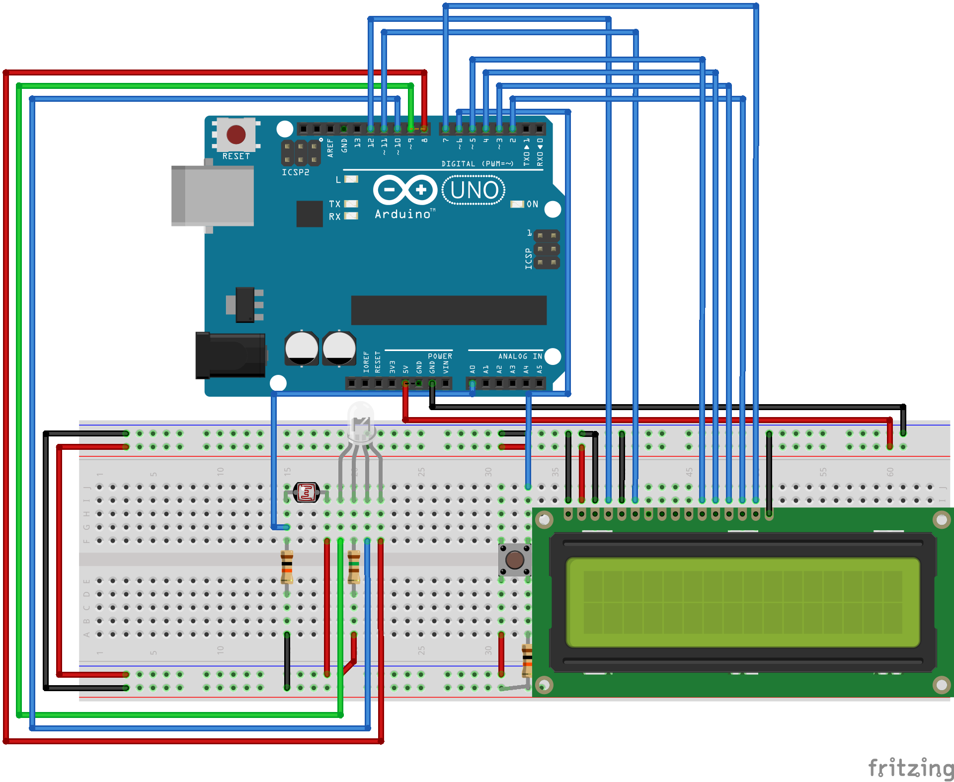
Electronic CircuitArising from objects, all the detection procedure happens in the electronic circuit, encompassing computational activity running in an Atmega328, which is hooked up in Arduino boards. Check the wiring from the schematics below.
The code follows the scheme above that uses a common anode RGB LED. That said, check whether your RGB LED is also a common anode, otherwise just invert the logic in the code.
Another important detail is that I am using only one resistor with the RGB LED. Since one color at a time will be lit, I put the resistor in the common anode, with an average resistance of the resistors that should have been with the cathodes - it is lazy, I know and I am sorry! When I went to buy project parts, they didn’t have everything I needed - but it is however very important to use the correct resistors with the cathodes in order to have fidelity in the collected RGB values with respect to RGB values in the computer. The way I did is not that bad, since the patterns are not distorted; they are just not the same colors we see in a computer screen (and as a human eye captures).
It can be observed from the schematics the adjacency between the RGB LED and the CdS Cell. That is because they must be isolated from ambient light (an oldie black film tube is the perfect piece), so calibration (explained in Programming) and recognition can be performed. Check the project video to see such components being isolated from ambient light.
Color TheoryColor perception performed by the electronic circuit is based in color theory concepts. Since there are no lenses (yet) involved, only objects with opaque (and matte) material should be considered, avoiding to deal with specular reflection of the LED. Diffuse reflection on the other hand is the key to perform color detection with lights. From an incident light, it is reflected in irregular surfaces, not creating that glowish effect that ruins the function of the CdS Cell.
Back to actual color theory, when light (of a certain color) reaches an object, it is reflected according to properties of that object’s color. For example, a red light reaching a yellow object will be reflected according to how much red exists in the composition of that yellow color - remember, we are talking about lights! - so it is expected to have a lot of red light being reflected, what makes sense when we think of the RGB composition of yellow (essentially red and green). However, when a blue light reaches the yellow object, no strong reflection is expected due to low presence of blue in the color composition.
Considering an additive color system, in which white and black are respectively presence and absence of every colors (more details here), there can be measured (with the CdS Cell) maximum and minimum reflections of each light from the RGB LED which will reach colored objects. That said, it is possible to perform the calibration in electronic components involved in the circuit. This is another key to get fidelity in detection, as well as to ensure a stable detection of patterns (avoiding outliers) - here is a golden tip: after calibrating, try (hard!) not to move or touch neither the electronic components (specially when they are placed in a breadboard), nor the piece you are using (you must use) to isolate components from ambient light.
ProgrammingFor calibration and recognition, the color sensor executes three iterations, once a colored object is exposed to the RGB LED and the CdS Cell. In the first iteration, red light hits the object and the program waits CdS cell to stabilize its sensing; the analog input is then read and the reflection of the red light is stored. The program iterates twice more for green and blue colors. The figure shown in Color theory gives a good visual explanation of this iterative process.
Concerning calibration, the iterative process mentioned above is performed twice: once for black color and once for white color. As explained in Color theory, this is for the detection of maximum and minimum - initially from near zero to near 1024, according to the reading resolution - reflections of red, green and blue lights, obtaining a true range to properly rescale to intervals [0, 255] (for informative purpose) and [0, 1] (the actual input to feed the neural network).
The waiting time to establish reading of the light sensor can vary according to each electronic component, so it is good to give a good delay to ensure a steady sensing. In my case, I gave a 500-millisecond delay, but it is worth to initially use a bigger value and then decreasing it until the verge of a non steady behavior.
In detection, the collected RGB values - ranging from 0 to 1 - feed an MLP, performing the actual color recognition. For the MLP running in Arduino, I am using Neurona - a library I wrote to easily use ANNs in arduino, which can be installed from Arduino IDE with the Library Manager. Check also this post for more details.
As mentioned earlier, the network is already trained and ready for detection in the project code. It was trained using the Playground I developed, embedding the adjusted weights to the code, so that Neurona library makes the network ready to operate.
TestsFor informative purposes, some colors were extracted from the dataset to perform some recognition tests:
Numbers outside the figure are used for identification and numbers inside the figure indicate misclassifications, referencing which colors were classified instead. These colors were printed in sulfite paper with an inkjet printer - check the tiny paper squares in the video in the beginning of this post - so the objects consist of opaque material, proper for color detection.


_3u05Tpwasz.png?auto=compress%2Cformat&w=40&h=40&fit=fillmax&bg=fff&dpr=2)
Comments