

Hardware components | ||||||
 |
| × | 1 | |||
Software apps and online services | ||||||
| ||||||
This walks you through the various files located at https://github.com/sparkfun/Blynk_Board_ESP8266 .
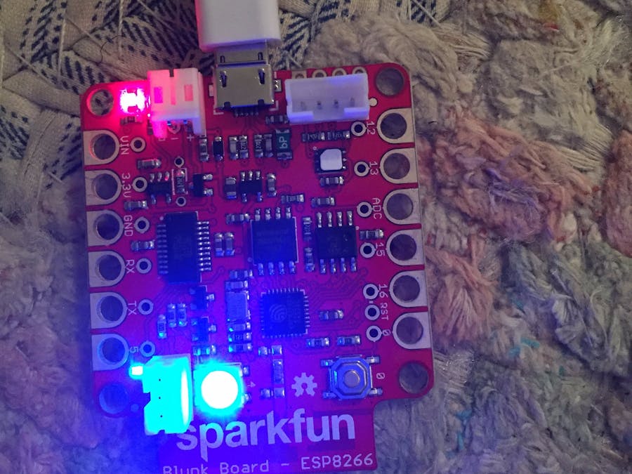
When I first got my Blynk board, I immediately installed the Blynk library in the Arduino IDE and uploaded ESP8266_Standalone.ino to connect it my new board internet. I was able to quickly connect the board to a project on my phone and control the physical ports, but suddenly my RGB status LED stopped working and none of my virtual ports worked anymore. EEEK!
The Blynk board comes preloaded with Sparkfun's firmware, which sets up the virtual ports and status LED. I found the firmware files on github and uploaded them back to my board. The virtual ports started working again, and I was able to go through the beginner projects found here. Afterwards, I still had a lot of questions about the firmware (and my RGB status LED still wasn't working) so I decided to dig through it and see what was up.
Sparkfun has made some nicely commented firmware.They even include the design files for the Blynk board.
You'll find the firmware files at https://github.com/sparkfun/Blynk_Board_ESP8266/tree/master/Firmware/BlynkBoard_Core_Firmware
Download the whole project as a zip file and copy it to your Arduino folder. Go ahead and upload the files to your board (follow the instructions here to get your Blynk board set up to be used with Arduino).
After installing the firmware, you'll have to connect your board to wifi via your phone again. You can do this by clicking on you project in the app and clicking "setup new device." Connect to the board over your phone's wifi, tell it your wifi password, and you're all set to blynk!
To better navigate the firmware's functionality, the source code is divided into a number of separate files. You'll need to keep all the files together because they require each other. These are the files you'll see:
Firmware Files and their FunctionsThe settings header file sets up various constant settings, including RGB colors and connection timeouts. You'll see it setting up the RGB LED, AKA WS2812, on pin 4.
The Blynk Firmware sketch is where setup()
and loop()
are defined, and it controls the RGB LED status indicator.
You'll notice that like the header files, this sketch includes adafruit's neopixel library (#include <Adafruit_NeoPixel.h>
). This is used to control the RGB LED, and I discovered that this was also where my RGB LED had stopped working. I had two different versions of the neopixel - one that came with the esp8266 library and one generic. The firmware was including the one that didn't include esp8266.c, and therein lay the problem.
You probably don't want to change anything here. It manages the hardware setup and EEPROM/flash reading/writing.
This file sets the configuration mode functions; AP and serial WiFi/Blynk configuration.
It's weird to see a .ino file full of HTML and CSS. That's because this file sets up the config server. Wait, what's the config server? The config server, or blynk Server, is responsible for all the communications between the smartphone and hardware.
So where can you see all this HTML served as a webpage? You can see it if you set up your own local blynk server, like they do in this tutorial:
This sets Blynk mode functions, including definition of all Blynk Board introductory experiments on sparkfun.
This is the sketch you want to change if you're changing things up in your project.
Want to change a virtual port? You can do it here! This sketch assigns a function to every one of the 32 virtual pins. For more information about how to use virtual pins, read this.
Say that you wanted to connect four servos to four joystick widgets in the app. You'll notice that a few of the virtual ports - V19, V22 and V26 are still available. You could connect these to three more servos that your joystick widgets can write to. You could also get rid of some of the functionality you aren't using for this project, say, tweeting, and use V23 and V24 as well.
If you've gotten this far, you're ready to start hacking!


_3u05Tpwasz.png?auto=compress%2Cformat&w=40&h=40&fit=fillmax&bg=fff&dpr=2)
Comments