

Hardware components | ||||||
 |
| × | 1 | |||
 |
| × | 1 | |||
Software apps and online services | ||||||
| ||||||
The Blynk board comes with a blue LED onboard, a WS2812 RGB LED (also known as a neopixel) onboard, and an expansion for even more LEDs!
Brighten and dim the blue onboard LEDLet's start by building a simple app to brighten and dim the blue onboard LED. First, make sure the default firmware is loaded on your board (it ships with this) and your phone is connected to your board.
The Blue LED is associated with Digital Pin 4. Add a slider (I've chosen Slider L, or large) and select D4. You can leave the default value range (0-255) or you can change it to any numbers that make sense to you (0-10?) Press the triangle to send to your board. You can now control the onboard blue LED with your slider!
Now, let's add in the RGB LED. No need to remove your blue LED from the app unless you want to. Add the ZERGBA!
The ZERGBA is the widget that lets you control the RGB LED's color by sliding your finger across a multicolored zebra.
To Split or To Merge?
You'll see two options on your ZERGBA - split or merge. Which one your choose depends what other widgets you're going to add, and whether you want to control brightness, color, or both.
When you choose merge, you control all the LEDs from one virtual port. In the default firmware, this port is V0. Choosing split gives you slightly more control. You're able to select the red, green and blue LEDs that make up the RGB LED individually. Or you can select "merge" and control each of the LEDs that make up the RG from a separate ZERGBA. Refer to the default firmware to see which virtual pins are being used to write which RGB values. Here, I've added one ZERGBA for each RGB value. Interesting...
Notice that controlling the LEDs individually (split) overrides controlling the LEDs from a single pin (merge).
Here, I've added a slider on each individual LED that makes up the RGB LED. When I do this, the ZERGBA on pin V0 no longer works.
Q. What happens if you add a single slider to your RGB LED (V0)? Will it control the color or the brightness?
A. It will control the color.
The brightness in the default firmware is controlled by virtual pin 15 (V15). Try adding a slider to it to control the RGB LED's brightness. Ouch! That RGB LED can get REALLY BRIGHT!
Control more LEDS!OK, now we're ready to control a bunch more LEDs on the expansion header.
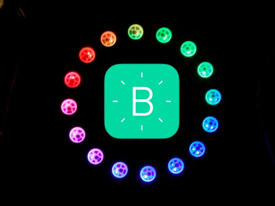
The 3 pin expansion can control an LED ring, like this one, or an LED strip, like this one. These can all be powered directly from the board's 3.3V power out, although the LEDs may not reach their maximum brightness.
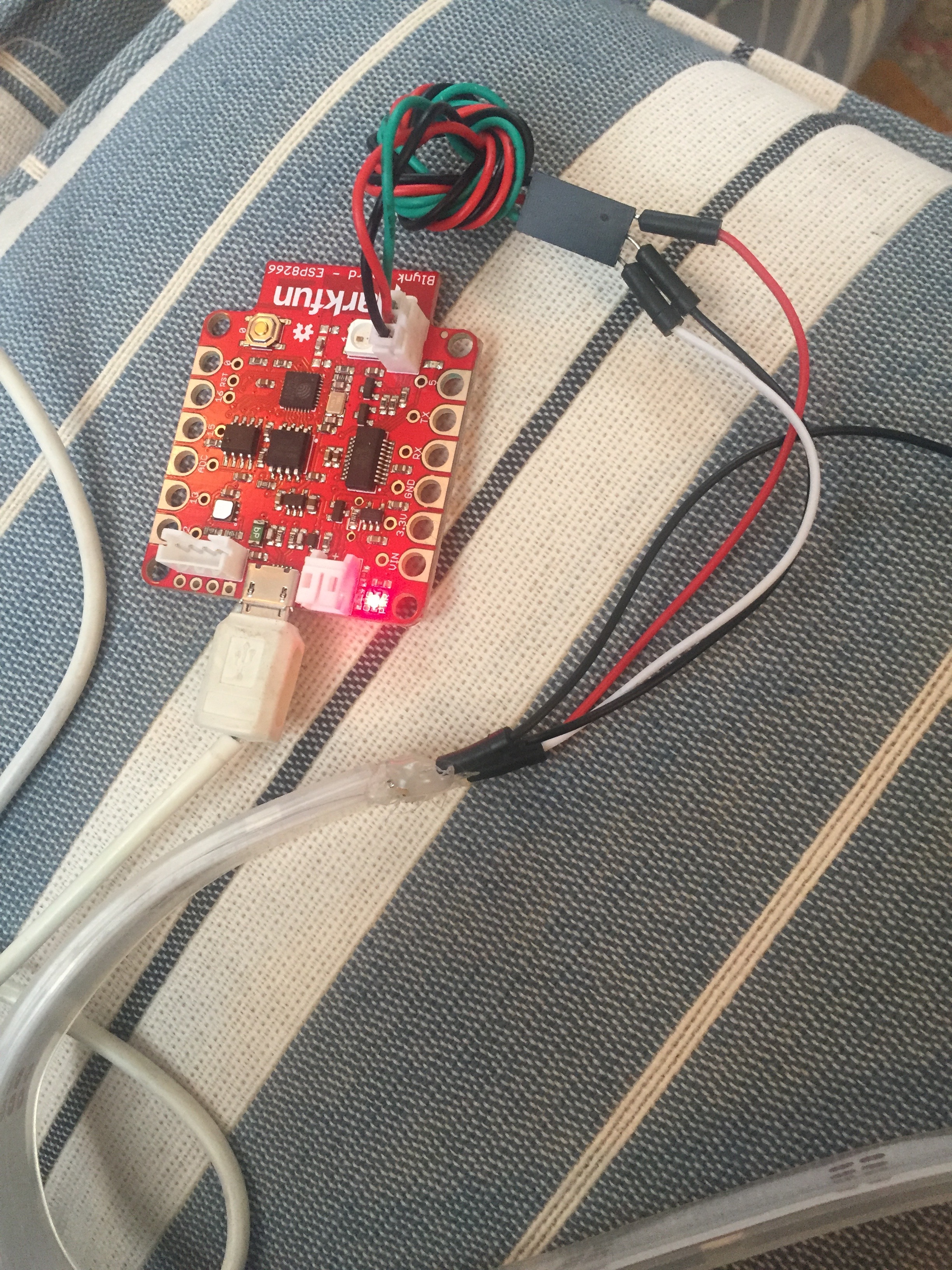
Plug your LED strip or ring into the expansion header.
The RGB LED and the expansion are both on digital Pin 4. Now test out your strip!
Make sure you have Adafruit's neopixel library downloaded and installed. Try loading one of the example sketches from the neopixel library, like strandtest. Enter the pin number (4) and number of neopixels in your strip.
#define PIN 4
#define NUMPIXELS      18
Be sure to count the onboard neopixel as well. For instance, my strip has 17 neopixels, so I use 18 as the total number. Whoa! Flashy lights!
Now say that you want to control your strip via the ZERGBA on your phone, or one of the sliders you've configured. With your LED strip still plugged in, upload the default firmware again and try to control RGB LED from the ZERGBA. Does it work?
For me, running the LED strip from the firmware was frustrating, because it seemed like sometimes it worked and sometimes it didn't. The default firmware attempts to query the number of LEDs using rgb.numPixels(); but it seems like it doesn't always get a good read. Even hardcoding the number of pixels into the sketch, by declaring #define NUMPIXELS 18 and then replacing rgb.numPixels(); with NUMPIXELS didn't always work.
I managed to get the ZERGBA with the LED strip working by writing my own Arduino sketch.
Now you can make your own phone controlled RGB lights! Awesome!
Further reading:


_3u05Tpwasz.png?auto=compress%2Cformat&w=40&h=40&fit=fillmax&bg=fff&dpr=2)
Comments