


Hardware components | ||||||
| × | 6 | ||||
| × | 6 | ||||
| × | 6 | ||||
| × | 2 | ||||
| × | 8 | ||||
| × | 4 | ||||
| × | 2 | ||||
| × | 1 | ||||
| × | 1 | ||||
| × | 1 | ||||
| × | 4 | ||||
| × | 2 | ||||
| × | 10 | ||||
| × | 8 | ||||
| × | 8 | ||||
| × | 8 | ||||
| × | 2 | ||||
| × | 24 | ||||
| × | 4 | ||||
| × | 1 | ||||
| × | 1 | ||||
| × | 1 | ||||
Software apps and online services | ||||||
 |
| |||||
Hand tools and fabrication machines | ||||||
 |
| |||||
| ||||||
| ||||||
| ||||||
| ||||||
 |
| |||||
In the world of sumo robotics, a traditional design reigns supreme: a single, powerful blade in the front, designed to push opponents out of the ring. But what if you could defy tradition and create a robot with a surprise? That's exactly what my project, The Two-BladesBrushless Sumo Robot, is all about. It's a next-level sumo robot designed to dominate the arena with two "fronts, " and the power of THOR High Power Outrunner Brushless Motors
My journey to building this innovative robot started with a simple question: How can I overcome the constraints of a competition and gain a strategic advantage? The most significant challenges were the dimensional and weight restrictions. The robot had to start within a compact 20x20cm space, but after the match begins, it's free to expand. This sparked a radical idea: instead of a fixed, flat design, why not have the blades stand up and then deploy? I designed a mechanism with two servos and arms that push the blades down at the start of the match, allowing my robot to unfold and double its effective pushing surface.
The second major hurdle was the weight limit. Standard brushed motors, while reliable, are heavy and less efficient. I needed a solution that would deliver immense power without the bulk. After extensive research, I found the perfect answer: a geared, outrunner brushless motor. These motors are a game-changer. Each one weighs only 70 grams but delivers a massive 87 watts of power. This is a huge leap forward compared to the 17-watt output of a typical 175-gram brushed motor. This incredible power-to-weight ratio gave me the freedom to design a more robust robot without sacrificing speed or torque.
The result is a highly agile and powerful sumo robot that can attack from multiple angles. It's not just a conventional pusher; it's a strategic machine with two fronts, ready to surprise any opponent. This project is a testament to the power of creative problem-solving and the endless possibilities of engineering.Motors and Sensors Testing
Final Results
V1 RobotBefore we start Making this amazing project its important to highlight that I spent around 1 year in the development of this amazing robot where I had a lot of challenges in controlling the Brushless motors and I have made 3 versions each version has different electronics such as the sensors and slightly different design. I have tried many sensors like the ultrasonic sensors in V1 robot and I was controlling the Motors using the PCA9685 Driver Module IIC Interface 16 Channel 12-Bit PWM Servo Motor Driver Board ControllerThen I made some modification on the design to replace the ultrasonic sensors because I have used 10 x sensors and the start making an issue called Crosstalk where Crosstalk is a type of interference that happens when multiple ultrasonic sensors are used in close proximity.
It occurs when a sensor's receiver picks up an echo from a pulse that was emitted by a different, neighboring sensor instead of its own.
This leads to inaccurate distance readings because the time it takes for the "wrong" echo to return doesn't correspond to the actual distance to the target for that specific sensor.
V2 RobotSo I decided to make V2 robot using different sensos and changing the Arduino NANO to ESP32 for faster response after I reached www.maxynos.net customer support where I bought the Motor controller then they confirmed that it can work with 3.3 volt PWM signal.the sensor I have used in V2 robot is the photoelectric Sensor 30 cm Adjustable M18 Diffuse photoelectric Switch Sensor
this video show the robot testing with ESP 32 and the Sensor
V3 RobotThe results where accepted, but the sensor size is big and the range is not as good as I want since we will build the BEST SUMO ROBOT EVER!so I had to change the ESP32 to Arduino NANO ESP32 as it can fit with smaller expansion board and replacing the sensors with TFmini plus sensors
Replacing V2 robot sensors with TFmini s sensors to become V3 Version
The first step is to start 3D printing the parts
you will need to assemble the blade with the blade holder STL file with Countersunk M3 screws length 8mm and the door hinge with flat head M6 screw x 14mm length
Jsumo blade No:01
the motor is Maxynos THOR 2318
In the website you will see different options you can select any option BUT NOT with GEAR RATIO 51 as it will not fit in the design!
since I first bout the motors the have a slightly different shaft color but still its the same if it fits perfectly in my design
in order to assemble the blade holder with the robot you will need
6X M6 x 30mm Hex Head Bolts Hexagon Screws and 6 X M6 Nuts
That's why the motor Ratio 51:1 dos not fit because there will be no space for the Lipo battery.
I tested the robot with Gear ratio 27:1 and motor KV 625KV!
If you want more Speed and Power you can go with the 1250KV motor version!
For the wheels there are many options where I recommend low shore hardness for better grip and you can use the below wheels from Maxynos, and Jsumo,
for my robot I used Maxynos PU 30A wheelsImportant to use WD-40 on the door hinge so it will be faster to move and rotate
For DC motors we usually use a motor driver but for Brushless motors the term of motor driver Called ESC - Electric Speed Controller.
To Learn how to control a brushless motor using Arduino please watch the below video I made for you! :))
Code in the Video and its work perfect with Arduino NANO ESP32 without any modifications :)
For Arduino Nano ESP32 you can Use any PWM Pin like D4, D2, or D3.
For ESP32 use the same Pin GPIO 4 or any other PWM Pin
#include <ESP32Servo.h>

Servo esc;
int escPin = 4;  // Choose any PWM-capable pin

void setup() {
  esc.setPeriodHertz(80);
  esc.attach(escPin, 1000, 2000);  // Min and Max pulse width in microseconds
  esc.writeMicroseconds(1500);     // Neutral (Stop)
  delay(2000);                     // Wait to arm ESC
}

void loop() {

  // Forward
  esc.writeMicroseconds(2000);
  delay(1000);

  // Stop (1500us)
  esc.writeMicroseconds(1500);
  delay(120);

  // Reverse
  esc.writeMicroseconds(1000);
  delay(1000);

  // Stop (1500us)
  esc.writeMicroseconds(1500);
  delay(120);
}My V1 robot used the Arduino Nano (ATmega328P), which—like the Mega and Uno relies on the stock Servo.h library. This library is constrained to output a fixed 50 Hz (20ms period) PWM signal, offering no easy frequency customization. This limitation resulted in severe issues, including signal instability (jitter) and the Electronic Speed Controllers (ESCs) losing calibration and causing sudden stops.
For V3, I upgraded to the ESP32 and the dedicated <ESP32Servo.h> library, which allows for flexible PWM frequency customization. Initial testing at the standard 50 Hz yielded the same poor, unstable results as the Nano. However, by increasing the frequency to 80 Hz, motor performance became perfectly stable and responsive. This confirms that the update rate of the control signal, enabled by the ESP32's superior hardware, was the critical factor for reliable control.
A significant challenge encountered was that the majority of tested ESCs were unidirectional (fixed-wing), only permitting motor rotation in one direction. This necessitated the selection of a bidirectional (reversible) ESC to achieve full motor control.
However, even after sourcing a bidirectional ESC, a disparity in performance was noted: the maximum reverse speed was significantly lower than the maximum forward speed. This required explicitly sourcing a bidirectional ESC with a 1:1 throttle ratio for consistent Forward, Stop, and Reverse operation.
Following extensive testing of several models, the Maxynos Bidirectional ESC 45A was selected as the optimal component, satisfying the 1:1 performance requirement.
Website:www.maxynos.net
The motor and ESC wires required cutting and direct soldering to ensure the compact fit so everything can fit inside.
As visible in the final (V3) robot, the ESCs were strategically mounted on the bottom plate of the chassis to maximize internal space utilization.
Proper wiring of the Brushless DC (BLDC) motor to the ESC is critical for correct operation.
Before soldering you need to understand how to connect a brushless motor with ESC!The ESC has 3 wires and the motor has also 3 wires the most important thing is to connect the middle with of the esc with the middle wire for the motor and for the left and right wires its okay to connect any from the ESC to any of the left and right wires on the motor.The configuration of left and right wires connection determines the direction of the motor's rotation. If the motor spins in the CW direction, you simply swap left to right wires and it will rotate CCW.
It is essential to note that each BLDC motor requires a dedicated ESC; multiple motors cannot be driven by a single ESC.
The wiring scheme used is shown in the image below:
You have 6 motors and you need 6 ESC's Each Motor connected a single ESC as below:
- Left wire (RED DOT) connect with A
- Middle wire (YELLOW DOT) connect with B
- Right Wire (GREEN DOT) connect with C
solder the wires as instructed and used double face to attached the ESC with the 3D printed base part.
Now you need to understand that the right side motors should rotate in the same direction so you need only 1 signal to be sent to all right side motors that's why we will connect the white wire from the upper part and call it the right side, and all white wires from the lower part and call it the left side wire.
// Define ESC pins (use only PWM-capable pins!)
const int pinRight = 2; // all upper 3 ESC's white wires connected in ESP nano pin 2
const int pinLeft = 3; // all lower 3 ESC's white wires connected in ESP nano pin 3
Now it is the time to test the motors and rotation direction by sending forward command and make sure all motors are rotating Forward!
#include <ESP32Servo.h>
// Create Servo objects for each motor
Servo escRight;
Servo escLeft;
// Define pins (use only PWM-capable pins!)
const int pinRight  = 2;
const int pinLeft   = 3;
void setup() {
// Set PWM frequency to 50Hz for ESCs
escRight.setPeriodHertz(80);
escLeft.setPeriodHertz(80);
// Attach ESCs with min/max PWM signal
escRight.attach(pinRight, 1000, 2000);
escLeft.attach(pinLeft, 1000, 2000);
// Arm ESCs with neutral signal
writeAll(1500);
delay(2000); // ESC arming delay
}
void loop() {
// Forward (1700us) for 0.9 sec
writeAll(1900);
delay(1600);
// Stop (1500us) for 0.12 sec
writeAll(1500);
delay(120);
// Reverse (1300us) for 0.9 sec
writeAll(1100);
delay(1600);
// Stop (1500us) for 0.12 sec
writeAll(1500);
delay(120);
}
// Helper function to write the same signal to all ESCs
void writeAll(int pulse) {
escRight.writeMicroseconds(pulse);
escLeft.writeMicroseconds(pulse);
}For ESCs that support forward and reverse, the range of the PWM signal is centered around a Neutral Point.
1. Stop (Neutral/Brake)The range is linear: 1000μs to 1500μs controls the speed of reverse, and 1500μs to 2000μs controls the speed of forward.
escRight.writeMicroseconds(1500); // the right motor will stop
escLeft.writeMicroseconds(1500); // the left motor will stop

delay(1000);

escRight.writeMicroseconds(2000); // the right motor will rotate forward at max speed
escLeft.writeMicroseconds(2000); // the left motor will rotate forward at max speed

delay(1000);

escRight.writeMicroseconds(1000); // the right motor will rotate backward at max speed
escLeft.writeMicroseconds(1000); // the left motor will rotate backward at max speed
This Video show you exactly how to perform the test! Enjoy :)
I know you may be a little confused because in the video, the wheels where attached in a different way but that because I was using the long shaft motor version from maxynos, and these motors are not compatible with this robot as it will exceed the 20 cm size limit, but I used them only for testing as I was developing the V3 robot
Long shaft is the Wrong motor not compatible20mm shaft motor is the right one to choose - Compatible
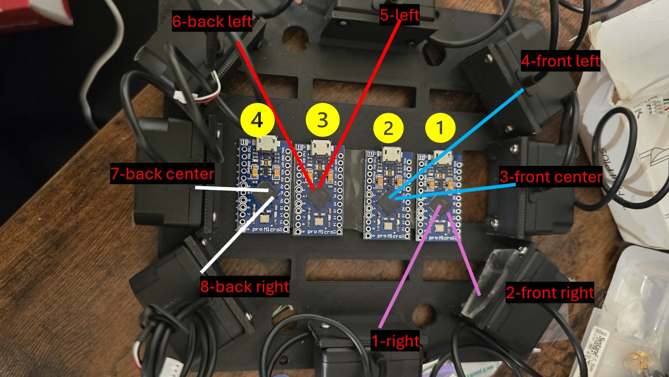
you will need now:8x TFmini sensors
4x Arduino leonardo mini
3D printed middle part
M3 Heat inserts
start inserting the heat inserts inside the Base part
The next step is to attached the mid plate part and install the sensors as below:
you will need 16x M2 Screws - 6 mm length as each sensor needs 2 screws
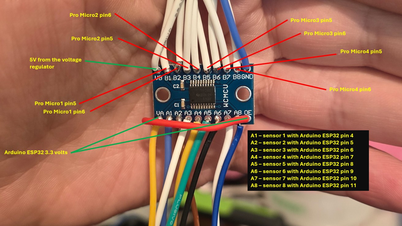
The A port accepts any supply voltage from 3.6 V. (OUTPUT TO ESP32)
The B port accepts any supply voltage from 5 V. (INPUT FROM MICRO MINI LEONARDOS)Now you need to use double face and attach the Leonardo Nano on the sensors holder part in a way that will let you connect the USB cable and upload the Arduino code as below:
Now we will add 2 x voltage regulators (5 V buck converter 5 Volts)
Lets explain the connections
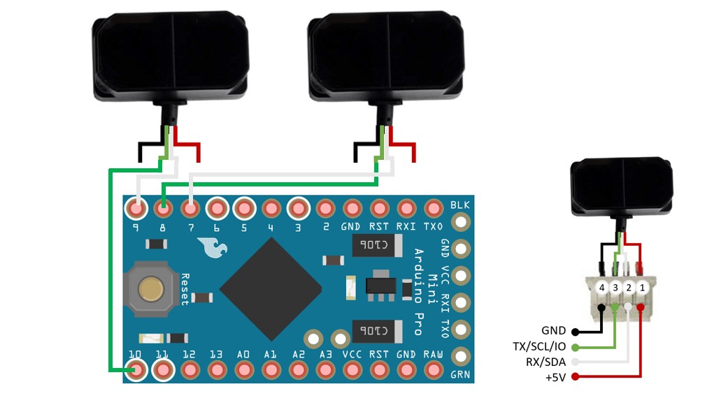
this sensor uses Serial Communication UART to output data a slandered Arduino UNO or NANO has only 1 software serial so you can only connect 1 sensor to 1 Arduino Nano Uno.
Why I choose Arduino Leonardo / Micro Atmega32U4?Because it has two software serials so you can connect 2 sensors with 1 Leonardo nano.
// Sensor 1: RX = 8 green, TX = 7 white
SoftwareSerial tfSerial1(8, 7);
// Sensor 2: RX = 10 green, TX = 9 white
SoftwareSerial tfSerial2(10, 9);
Connect the sensors as you see in the above picture
Full code for the sensors and show results on the serial monitor.
Use the below code to test Each Pro Micro Leonardo separately where you should see the results for 2 sensors for each MCU.
#include <SoftwareSerial.h>
#include "TFMini.h"
#define TIMER_THRESHOLD 300     // Timeout in milliseconds
int rangeLimit = 40;            // Detection threshold in cm
// Sensor 1: RX = 8 green, TX = 7 white
SoftwareSerial tfSerial1(8, 7);
TFMini tfmini1;
// Sensor 2: RX = 10green, TX = 9 white
SoftwareSerial tfSerial2(10, 9);
TFMini tfmini2;
// Output pins
const int output1 = 5;
const int output2 = 6;
void setup() {
Serial.begin(9600);
tfSerial1.begin(TFMINI_BAUDRATE);
tfSerial2.begin(TFMINI_BAUDRATE);
tfmini1.begin(&tfSerial1);
tfmini2.begin(&tfSerial2);
pinMode(output1, OUTPUT);
pinMode(output2, OUTPUT);
}
// Read and parse data frame from TFMini
void getTFminiData(SoftwareSerial& serial, int* distance, int* strength, bool* validReading) {
static char i = 0;
char j = 0;
int checksum = 0;
static int rx[9];
if (serial.available()) {
rx[i] = serial.read();
if (rx[0] != 0x59) {
i = 0;
} else if (i == 1 && rx[1] != 0x59) {
i = 0;
} else if (i == 8) {
for (j = 0; j < 8; j++) {
checksum += rx[j];
}
if (rx[8] == (checksum % 256)) {
*distance = rx[2] + rx[3] * 256;
*strength = rx[4] + rx[5] * 256;
*validReading = true;
}
i = 0;
} else {
i++;
}
}
}
// Read one sensor and print status
void readSensor(TFMini& sensor, SoftwareSerial& serial, int pinOut, const char* label) {
int distance = 0, strength = 0;
bool validReading = false;
unsigned long start = millis();
serial.listen();  // Activate listening on this serial port
// Try to read new data within timeout
while (!validReading && (millis() - start < TIMER_THRESHOLD)) {
getTFminiData(serial, &distance, &strength, &validReading);
}
if (validReading) {
if (distance <= rangeLimit) {
digitalWrite(pinOut, HIGH);
Serial.print(label); Serial.println(": HIGH (Target Detected)");
} else {
digitalWrite(pinOut, LOW);
Serial.print(label); Serial.println(": LOW (Target Out of Range)");
}
Serial.print(label); Serial.print(" Distance: ");
Serial.print(distance); Serial.println(" cm");
} else {
digitalWrite(pinOut, LOW);
Serial.print(label); Serial.println(": TIMEOUT (No Response)");
}
}
void loop() {
readSensor(tfmini1, tfSerial1, output1, "Sensor 1");
readSensor(tfmini2, tfSerial2, output2, "Sensor 2");
delay(100);
}Connect all A port wires from the voltage logic level shifter to the Arduino Nano ESP32 as demonstrated in the picture below:
- A1 - sensor1 with Arduino ESP32 pin 4
- A2 - sensor2 with Arduino ESP32 pin 5
- A3 - sensor3 with Arduino ESP32 pin 6
- A4 - sensor4 with Arduino ESP32 pin 7
- A5 - sensor5 with Arduino ESP32 pin 8
- A6 - sensor6 with Arduino ESP32 pin 9
- A7 - sensor7 with Arduino ESP32 pin 10
- A8 - sensor8 with Arduino ESP32 pin 11
Connect all wires from the voltage logic level shifter to the Arduino Nano ESP32 using the below Code:
#include <ESP32Servo.h>
Servo myServo;
const int servoPin = 12;
// Individual sensor pins
const int sensor1 = 4;
const int sensor2 = 5;
const int sensor3 = 6;
const int sensor4 = 7;
const int sensor5 = 8;
const int sensor6 = 9;
const int sensor7 = 10;
const int sensor8 = 11;
void setup() {
Serial.begin(115200);
// Set all sensor pins as input
pinMode(sensor1, INPUT);
pinMode(sensor2, INPUT);
pinMode(sensor3, INPUT);
pinMode(sensor4, INPUT);
pinMode(sensor5, INPUT);
pinMode(sensor6, INPUT);
pinMode(sensor7, INPUT);
pinMode(sensor8, INPUT);
// Servo setup and single open/close action
myServo.setPeriodHertz(50); // 50 Hz standard servo
myServo.attach(servoPin, 500, 2400);
myServo.write(180);  // Open
delay(500);
myServo.write(0);   // Close
delay(500);
myServo.detach();
}
void loop() {
int s1 = digitalRead(sensor1);
int s2 = digitalRead(sensor2);
int s3 = digitalRead(sensor3);
int s4 = digitalRead(sensor4);
int s5 = digitalRead(sensor5);
int s6 = digitalRead(sensor6);
int s7 = digitalRead(sensor7);
int s8 = digitalRead(sensor8);
Serial.print("Sensor 1: "); Serial.println(s1);
Serial.print("Sensor 2: "); Serial.println(s2);
Serial.print("Sensor 3: "); Serial.println(s3);
Serial.print("Sensor 4: "); Serial.println(s4);
Serial.print("Sensor 5: "); Serial.println(s5);
Serial.print("Sensor 6: "); Serial.println(s6);
Serial.print("Sensor 7: "); Serial.println(s7);
Serial.print("Sensor 8: "); Serial.println(s8);
Serial.println("-------------------------");
delay(300);  // Short pause between readings
}- Mount the servo motors on the Cover 3D printed Part
- Remove the arm
- Connect both servo's signal wires to Arduino Nano esp32 Pin 12
- Connect both servo's positive wires to the 5V regulator
- Connect both servo's negative wires to the 5V regulator
- as I said before one regulator for the servo motors and the second ono for powering all other electronics including sensors, Arduino ESP32, and all Pro Micro Leonardo MCU's
- Use the Arduino code to set the angle to Zero
- Add the servo motors arms and install the 3D printed Arms using screws
#include <ESP32Servo.h> // Include the ESP32Servo library
Servo myServo;  // Create a servo object
const int servoPin = 12;    // Define the pin connected to the servo
const int openAngle = 180;  // Define the angle to open the servo
const int closeAngle = 0;   // Define the angle to close the servo
bool actionDone = false;  // Flag to ensure the action happens only once
void setup() {
myServo.attach(servoPin);   // Attach the servo to the specified pin
myServo.write(closeAngle);  // Set the servo to the initial position (0°)
delay(3300);                // Small delay to ensure the servo reaches its starting position
}
void loop() {
if (!actionDone) {           // Check if the action has already occurred
myServo.write(openAngle);  // Move the servo to the open angle
delay(800);                // Wait for 3.3 seconds
myServo.write(closeAngle);  // Move the servo back to the closed angle
delay(800);                // Wait for 3.3 seconds
actionDone = true;  // Set the flag to true to prevent repeating
}
// Do nothing after the action is completed
}upload the full code and you should get the same results as mine
#include <ESP32Servo.h>
// Create Servo objects for each motor
Servo escRight;
Servo escLeft;
Servo myServo;
// Define ESC pins (use only PWM-capable pins!)
const int pinRight = 2;
const int pinLeft = 3;
// Define servo motor pin
const int servoPin = 12;
// Individual sensor pins
const int sensor1 = 4;
const int sensor2 = 5;
const int sensor3 = 6;
const int sensor4 = 7;
const int sensor5 = 8;
const int sensor6 = 9;
const int sensor7 = 10;
const int sensor8 = 11;
unsigned long attackTimer = 0;
bool actionDone = false; // Flag to ensure the action happens only once
void setup() {
//Serial.begin(115200);
// Set PWM frequency to 80Hz for ESCs
escRight.setPeriodHertz(80);
escLeft.setPeriodHertz(80);
// Attach ESCs with min/max PWM signal
escRight.attach(pinRight, 1000, 2000);
escLeft.attach(pinLeft, 1000, 2000);
// Servo motor setup and single open/close action
myServo.setPeriodHertz(50); // 50 Hz standard servo
myServo.attach(servoPin, 500, 2400);
delay(4000);
myServo.write(180); // Open
delay(500);
myServo.write(15); // Close
delay(500); // Wait for 3.3 seconds
// Set all sensor pins as input
pinMode(sensor1, INPUT);
pinMode(sensor2, INPUT);
pinMode(sensor3, INPUT);
pinMode(sensor4, INPUT);
pinMode(sensor5, INPUT);
pinMode(sensor6, INPUT);
pinMode(sensor7, INPUT);
pinMode(sensor8, INPUT);
//myServo.detach();
}
void loop() {
if (!actionDone) { // Check if the action has already occurred
writeAll(1500);
delay(200);
writeAll(2000);
delay(200);
writeAll(1500);
delay(600);
actionDone = true; // Set the flag to true to prevent repeating
}
int s1 = digitalRead(sensor1);
int s2 = digitalRead(sensor2);
int s3 = digitalRead(sensor3);
int s4 = digitalRead(sensor4);
int s5 = digitalRead(sensor5);
int s6 = digitalRead(sensor6);
int s7 = digitalRead(sensor7);
int s8 = digitalRead(sensor8);
if (s3 == 1) {
writeAll(1100); // Move forward to attack
}
else if (s7 == 1) {
writeAll(1900); // Move forward to attack
}
else if ((s1 == 1) || (s5 == 1)) {
attackTimer = millis();
while (((!digitalRead(sensor3)) || (!digitalRead(sensor7))) && ((millis() - attackTimer) < 600)) {
escRight.writeMicroseconds(1800);
escLeft.writeMicroseconds(1200);
if ((digitalRead(sensor3) == 1) || (digitalRead(sensor7) == 1)) {
break;
}
}
}
else if ((s2 == 1) || (s6 == 1)) {
attackTimer = millis();
while (((!digitalRead(sensor3)) || (!digitalRead(sensor7))) && ((millis() - attackTimer) < 300)) {
escRight.writeMicroseconds(1800);
escLeft.writeMicroseconds(1200);
if ((digitalRead(sensor3) == 1) || (digitalRead(sensor7) == 1)) {
writeAll(1500);
break;
}
}
}
else if ((s4 == 1) || (s8 == 1)) {
attackTimer = millis();
while (((!digitalRead(sensor3)) || (!digitalRead(sensor7))) && ((millis() - attackTimer) < 300)) {
escRight.writeMicroseconds(1200);
escLeft.writeMicroseconds(1800);
if ((digitalRead(sensor3) == 1) || (digitalRead(sensor7) == 1)) {
writeAll(1500);
break;
}
}
}
else {
// If no enemy detected, stop
writeAll(1500);
}
}
// Helper function to write the same signal to all ESCs
void writeAll(int pulse) {
escRight.writeMicroseconds(pulse);
escLeft.writeMicroseconds(pulse);
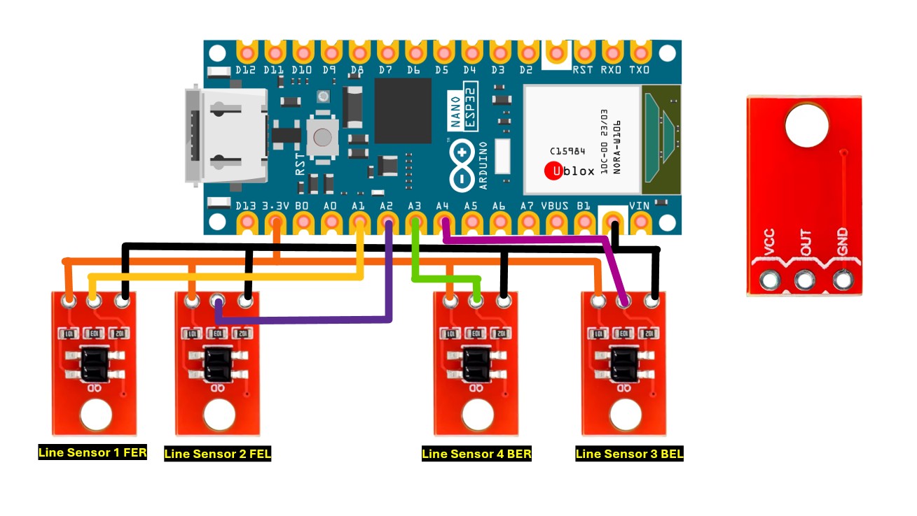
}Final touch - Adding the line Sensors
this is a digital sensor and need a digital pin from the ESP32 to detect the white edge of the Dohyo
https://www.aliexpress.us/item/3256805580312633.html?spm=a2g0o.order_list.order_list_main.5.14f818028HKkFU&gatewayAdapt=glo2usa
https://www.jsumo.com/micro-line-sensor-ml1
- This sensor can work with 3.3 volts and connected directly to the ESP32 3.3 volts VCC
- GND is common
- Signals to any Arduino Nano ESP32 digital pins
The idea is when this sensor detects the white line then the robot will reverse the wheels rotation direction
Upload the Final code with Adding the Line sensors and you will have your robot Ready.
#include <ESP32Servo.h>
// Create Servo objects for each motor
Servo escRight;
Servo escLeft;
Servo myServo;
// Define ESC pins (use only PWM-capable pins!)
const int pinRight = 2;
const int pinLeft = 3;
// Define servo motor pin
const int servoPin = 12;
// Individual sensor pins
const int sensor1 = 4;
const int sensor2 = 5;
const int sensor3 = 6;
const int sensor4 = 7;
const int sensor5 = 8;
const int sensor6 = 9;
const int sensor7 = 10;
const int sensor8 = 11;
unsigned long attackTimer = 0;
bool actionDone = false;  // Flag to ensure the action happens only once
// edge sensors
int ferValue;
int felValue;
int berValue;
int belValue;
// Define pins for edge sensors, these edge sensors with output HIGH if a white color is detected
const int FER_PIN = A1;  // Front Edge Right
const int FEL_PIN = A2;  // Front Edge Left
const int BER_PIN = A3;  // Back Edge Right
const int BEL_PIN = A4;  // Back Edge Left
// Variables to store the last edge speed for searching for the opponent
int lastLeftEdgeSpeed = 1630;
int lastRightEdgeSpeed = 1610;
void setup() {
//Serial.begin(115200);
// Set PWM frequency to 80Hz for ESCs
escRight.setPeriodHertz(80);
escLeft.setPeriodHertz(80);
// Attach ESCs with min/max PWM signal
escRight.attach(pinRight, 1000, 2000);
escLeft.attach(pinLeft, 1000, 2000);
// Servo motor setup and single open/close action
myServo.setPeriodHertz(50);  // 50 Hz standard servo
myServo.attach(servoPin, 500, 2400);
delay(4000);
myServo.write(180);  // Open
delay(500);
myServo.write(15);  // Close
delay(500);         // Wait for 3.3 seconds
// Set all sensor pins as input
pinMode(sensor1, INPUT);
pinMode(sensor2, INPUT);
pinMode(sensor3, INPUT);
pinMode(sensor4, INPUT);
pinMode(sensor5, INPUT);
pinMode(sensor6, INPUT);
pinMode(sensor7, INPUT);
pinMode(sensor8, INPUT);
//Edge sensors
pinMode(FER_PIN, INPUT);
pinMode(FEL_PIN, INPUT);
pinMode(BER_PIN, INPUT);
pinMode(BEL_PIN, INPUT);
}
void loop() {
if (!actionDone) {  // Check if the action has already occurred
writeAll(1500);
delay(200);
writeAll(2000);
delay(200);
writeAll(1500);
delay(600);
actionDone = true;  // Set the flag to true to prevent repeating
}
int s1 = digitalRead(sensor1);
int s2 = digitalRead(sensor2);
int s3 = digitalRead(sensor3);
int s4 = digitalRead(sensor4);
int s5 = digitalRead(sensor5);
int s6 = digitalRead(sensor6);
int s7 = digitalRead(sensor7);
int s8 = digitalRead(sensor8);
//  Edge digital sensor  values
ferValue = digitalRead(FER_PIN);
felValue = digitalRead(FEL_PIN);
berValue = digitalRead(BER_PIN);
belValue = digitalRead(BEL_PIN);
if (s3 == 1) {
writeAll(1100);  // Move forward to attack
} else if (s7 == 1) {
writeAll(1900);  // Move forward to attack
}
else if (ferValue == 0) {  // Front Edge Right detected
lastRightEdgeSpeed = 1330;
lastLeftEdgeSpeed = 1350;
escRight.writeMicroseconds(1330);
escLeft.writeMicroseconds(1350);
delay(400);
} else if (felValue == 10) {  // Front Edge Left detected
lastRightEdgeSpeed = 1350;
lastLeftEdgeSpeed = 1330;
escRight.writeMicroseconds(1350);
escLeft.writeMicroseconds(1330);
delay(400);
} else if (berValue == 0) {  // Back Edge Right detected
lastRightEdgeSpeed = 1630;
lastLeftEdgeSpeed = 1590;
escRight.writeMicroseconds(1630);
escLeft.writeMicroseconds(1590);
delay(400);
} else if (belValue == 0) {  // Back Edge Left detected
lastRightEdgeSpeed = 1590;
lastLeftEdgeSpeed = 1630;
escRight.writeMicroseconds(1590);
escLeft.writeMicroseconds(1630);
delay(400);
}
else if ((s1 == 1) || (s5 == 1)) {
attackTimer = millis();
while (((!digitalRead(sensor3)) || (!digitalRead(sensor7))) && ((millis() - attackTimer) < 600)) {
escRight.writeMicroseconds(1800);
escLeft.writeMicroseconds(1200);
if ((digitalRead(sensor3) == 1) || (digitalRead(sensor7) == 1)) {
break;
}
}
} else if ((s2 == 1) || (s6 == 1)) {
attackTimer = millis();
while (((!digitalRead(sensor3)) || (!digitalRead(sensor7))) && ((millis() - attackTimer) < 300)) {
escRight.writeMicroseconds(1800);
escLeft.writeMicroseconds(1200);
if ((digitalRead(sensor3) == 1) || (digitalRead(sensor7) == 1)) {
writeAll(1500);
break;
}
}
} else if ((s4 == 1) || (s8 == 1)) {
attackTimer = millis();
while (((!digitalRead(sensor3)) || (!digitalRead(sensor7))) && ((millis() - attackTimer) < 300)) {
escRight.writeMicroseconds(1200);
escLeft.writeMicroseconds(1800);
if ((digitalRead(sensor3) == 1) || (digitalRead(sensor7) == 1)) {
writeAll(1500);
break;
}
}
} else {
escRight.writeMicroseconds(lastRightEdgeSpeed);
escLeft.writeMicroseconds(lastLeftEdgeSpeed);
}
}
// Helper function to write the same signal to all ESCs
void writeAll(int pulse) {
escRight.writeMicroseconds(pulse);
escLeft.writeMicroseconds(pulse);
}
Good Luck! :)


Comments