


Hardware components | ||||||
 |
| × | 1 | |||
Software apps and online services | ||||||
| ||||||
Every periodic signal can be described as a sum of sine waves with different frequencies, amplitudes, and phase shifts. This gives possibility of synthesizing signals with sine waves and analyze all kinds of signals to determine sine waves that makes the signal.
Decomposition of signal shape (data in time domain) to sine waves that make the signal (data in frequency domain) is done by FFT (Fast Fourier Transform). This algorithm is implemented in Digilent WaveForms.
Frequencies of the sine waves are strictly described. Every periodic signal has its own frequency - base frequency. It is equal to frequency of the first sine wave. Next sine waves in the sum have frequencies multiplicated by its index - for example, second sine wave has frequency equal to 2 * base frequency.
Index of the sine wave is called a harmonic. I will show how to measure amplitudes of harmonics in signal, that is, amplitude of specific sine wave in signal.
Unfortunately, we can't measure phase of the sine waves, because phase FFT algorithm is not yet implemented in Digilent WaveForms (it's possible to do this in WaveForms SDK, FFT needs only samples of the signal).
Torun this example, you need AnalogDiscovery 2 and PC.
Connect Analog Discovery 2 to your computer.
Connect 1+ (oscilloscope positive input) to W1 (waveform generator output) and 1-(oscilloscope negative input) to GND (ground).
We will play waveforms by WaveGen and observe shapes of the signal and measure harmonics (FFT) using Scope.
WaveformGenerator:
1. To launch the Waveform Generator, click on the Wavegen button.
2. Switch to the custom mode - we will implement additivegenerator.
3. Click on New, paste the code provided below to the script field. By modifying amp and phase values, we will generate different shapes of signals. If you click the generate button, you will see the generated shape.
var amp =[1,0,0,0,0,0,0,0,0,0];     //amplitudevalues from 0 to 1 (0-100%)
var ph =  [0,0,0,0,0,0,0,0,0,0];     //phase values from 0 to 1 (0-360degrees)

Y = amp[0] *sin((1 * 2*PI*X) + 2*PI*ph[0])
+ amp[1] *sin((2 * 2*PI*X) + 2*PI*ph[1])
+ amp[2] *sin((3 * 2*PI*X) + 2*PI*ph[2])
+ amp[3] *sin((4 * 2*PI*X) + 2*PI*ph[3])
+ amp[4] *sin((5 * 2*PI*X) + 2*PI*ph[4])
+ amp[5] *sin((6 * 2*PI*X) + 2*PI*ph[5])
+ amp[6] *sin((7 * 2*PI*X) + 2*PI*ph[6])
+ amp[7] *sin((8 * 2*PI*X) + 2*PI*ph[7])
+ amp[8] *sin((9 * 2*PI*X) + 2*PI*ph[8])
+ amp[9] * sin((10 * 2*PI*X) + 2*PI*ph[9]);
1. To launch the Oscilloscope, click on the Scope button.
2.Trigger options (Fig. 10 below):
Source: Channel 1;
Condition: rising;
Level: 0V.
3.Time options (Fig. 11 below):
Position: 0s;
Base: 1ms/div.
4.Unclick Channel 2.
5.Channel options:
Offset: 0V;
Range: 500mV/div;
Click on the sprocket wheel button and unclick Noise checkbox.
6. Click on View->FFT to show FFT window.
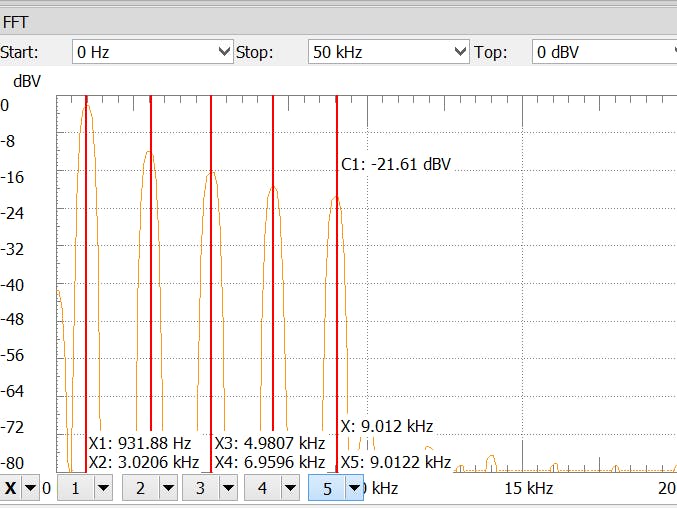
7.FFT options:
Start: 0Hz;
Stop: 50kHz;
Top: 0dBV;
Bottom: -80dBV
The setup is done, so we can now take some measurements.
ExamplesofOtherWaveforms:


Comments