


Hardware components | ||||||
 |
| × | 1 | |||
| × | 1 | ||||
| × | 1 | ||||
| × | 1 | ||||
| × | 1 | ||||
 |
| × | 3 | |||
| × | 1 | ||||
| × | 1 | ||||
 |
| × | 3 | |||
 |
| × | 1 | |||
| × | 1 | ||||
| × | 1 | ||||
| × | 6 | ||||
| × | 2 | ||||
 |
| × | 2 | |||
 |
| × | 1 | |||
Software apps and online services | ||||||
 |
| |||||
 |
| |||||
Hand tools and fabrication machines | ||||||
 |
| |||||
 |
| |||||
Update 2025: I revised the overall design to allow for a better gear pulley - the original one used to slip due to changing cord lengths due to temperature changes and stretching.
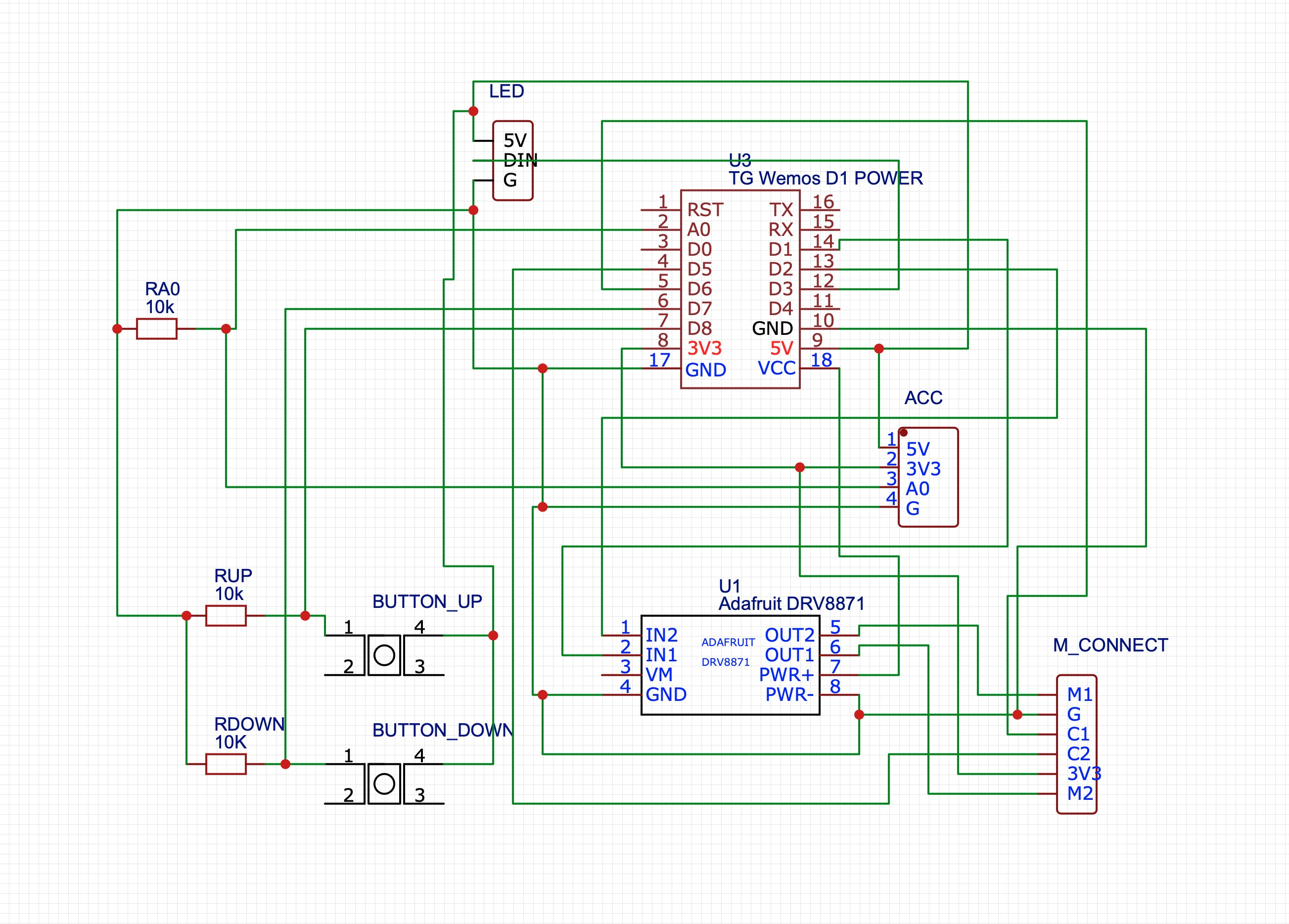
I have also added a magnetic reed switch on A0 and G (2 male headers on ACC in the schematic) and populated a 10k resistor on RA0 to ensure the doors are not open when the blind operates - it will also send a mqtt message as a contact sensor optionally. You can activate this feature by setting #define CONTACT 1 in the source code.
It was one of my more challenging projects to automate my home but also the most rewarding as I have 8 (!) blinds/shades at my home wanted to be motorised to make the most of the natural light. 4 of them are quite large and heavy at 1.5 meters width and 3 meters length!
Looking at commercially available options I could have spend thousands to get shades with inbuilt motors (which are superior I have to admit) or around $200 for a similar retrofit unit made by various commercial manufacturers. But looking into the these options most of them didn't have any Apple Homekit compatibility or sometimes even buttons to manually control them - and I was looking for something more affordable!
I came across a promising design from cabuu which was well documented, had buttons, used off the shelf parts and most importantly used a motor with an encoder that was quite affordable. I ordered a couple of pcb's of him to test it out.
http://mangetout.net/cabuu/2019/03/30/blind-controller-v2-announced/
First TestAfter 3D printing the housing and soldering all the parts together to my surprise the 12v motor was underpowered by using a motor driver rated at max 10V.
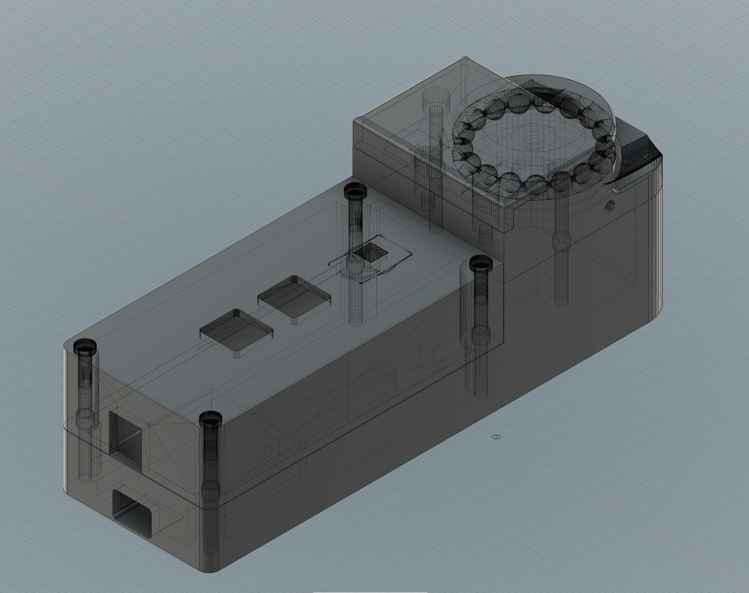
I found a few details of the housing needed refining as well - e.g. adding grooves for the chain to the Gear Surround or mounting holes to the main body as well as changing the sizing of some parts.
As my blinds are quite large and heavy I wanted to run the motor at 12V and decided to use the Adafruit DRV8871 motor driver due to it's similar size and functionality. As I didn't want to completely redesign the housing I created a circuit board based on the original design but with the more powerful motor driver.
Revised circuit boardI am not going too much in detail how to solder but here is quick summary of my approach and order:
- 2 x Buttons
- 2 x 10k capacitors for RDOWN & RUP - leave RAO (Resistor Analogue Out) empty
- Female header pins for the microcontroller and 2 for the power supply
- Male header pins for the motor driver - I am aware it's not ideal because of the buttons on the other side 4 pins need to be soldered on the surface rather through the hole
- Motor driver board, I had to solder them directly due to the lack of space by the motor encoder
- Female stackable header for D1 Power shield, 2 Male header pins for the 12V Power supply (watch for the right direction and orientation)
- Male headers for the Wemos D1 mini (watch for the right direction and orientation)
- Attachment wires the motor - approx. 5cm - coming out the the button side of the pcb
- 3 wires for the WS2812b LED - approx. 3cm - coming out the the button side of the pcb > solder it to a cut LED from the strip
Please note ACC for Accessory is unused. It was meant to attach a light sensor to the Analog pin in future versions. It's easy to add but didn't see the benefit yet.
It should make more sense once you have all the parts printed and electronics assembled in front of you. Here are the steps:
- Use 2 x M3 - 10mm bolts to attach the motor to the Gear Surround
- Heat and insert 2 x M3 - 4-6mm brass heat inserts to the Main body for the Gear Surround
- Superglue or tape the WS2812B LED to the Button Housing.
- Place circuit board into the Button Surround loosely
- Make sure to attach the wires to the motor before using 2 x M3 - 32mm bolts to secure the Gear Surround to the main body - it's a tight fit for the cable
- Place the circuit board to it's designated area of the main body and use 4 x M3 - 24-32mm size fitting (plastic) screws to attach them to the main body. Don't over tighten, just make sure it's not wobbling and the buttons can be pressed.
- Place 6mm Gear Coupler to the Gear. It's a tight fit and secure with 2 - 4 short flat screws. Make sure to be able to access the small bolt with the hex key beforehand!
Before uploading the code make sure to enter the MQTT credentials (MQTT server, user, password) in Arduino IDE. I had to use the ESP8266 library version 2.42 as the latest version gave me issues. All the other libraries needed are the following and the most recent should work:
The host is called 'myblind' by default but can be changed.
You can also change the direction of the Motor (MOTORWIRE) and wiring of the Encoder (ENCODERWIRE) - use 1 or 0 to do so but leave it for now.
Once the code is uploaded successfully you shall be able to see and connect to 'myBlind' wifi network via WiFiManager. Connect and enter your wifi details and if done correctly it will connect to your local wifi network and will be ready to run!
You will be able to upload future updates via web server which its useful if you use more than one.
Attention: After saving the WiFi credentials successfully,keep the DOWN Button pressed to Reset the EEPROM to Default settings.
Otherwise it will crash as the controller tries to read saved EEPROM values initially which are not there yet! If it didn't work the first time unplug it and power it up again while keeping the DOWN Button pressed.
For now keep the computer connected and attach the 12V Power adapter to power up the motor!
Use the Serial Monitor at 115200 baud. A long press of the UP Button should rotate the Motor clockwise and the Encoder value of the current position (Pos) should go up too. If that's not the case change the ENCODERWIRE value to the opposite number (either 1 or 0). The reason behind this is some of the motor encoders are wired one way and some the other.
It's the same obviously using the DOWN Button but the other way around.
Attachment to the existing blindYou best of assembling the unit initially and testing it without being properly attached it to the window or frame yet. Make sure the flat bit of the Motorshaft is facing up and attach the chain to the motor via the Gear (with the Gear coupler). Tighten the gear coupler to the motorshaft with the hex and headless bolt that comes with it. Not too tight!
Due to the chain grooves the blind chain is able twist 90 degrees to either side so we can mount the controller parallel to the blind - so directly on the wall or frame. How you want it to turn is up to you but my settings are MOTORWIRE on 0 turns it clockwise for a righthand side installation and MOTORWIRE 1 counterclockwise for a lefthand side installation. But you can play with that. Just make sure the Position value goes up when pressing UP and down when pressed DOWN!
Make sure the chain is tightened evenly and mark the 3 spots on the wall for the holes. I highly recommend marking spots at the low side of the mounting holes as you will most likely end up needing them to tighten the chains later on by pulling the unit further down. Metal chains are more susceptible to stretching over time.
Once you are happy with the height all that's left to do is to secure the main body with screws and preferably washers to the wall/frame! Put on the Gear surrounds, Gear and chain, Button Surrounds and connect it when the 12V Power supply!
A continued long press UP will move the blind up.
A continued long press DOWN will move the blind down.
Set up Position of Blind (100%)
A continued long press UP will move the blind up - keep pressing UP until it reaches the up position followed quick short press UP. LED flashes 3 x Blue, 1 x Purple to confirm new up position
Set downPosition of Blind (0%)
A continued long press DOWN will move the blind down - keep pressing DOWN until it reaches the down position followed quick short press DOWN. LED flashes 3 x Yellow, 1 x Purple to confirm new up position
Ignore EEPROM values Press UP BUTTON for 5 seconds while powering up.
It's followed by the LED flashing 3 x Pink
Reset EEPROM values Press DOWN BUTTON for 5 seconds while powering up.
It's followed by the LED flashing 3 x Red
Reset All Settings incl. WiFi credentials Press UP + DOWN BUTTON for 5seconds while powering up.
It's followed by the LED flashing 3 x Green, 4 x Yellow, 5 x Orange, 6 x Red
LED sequence during normal Start Up
Red = initially when powered on
Orange = connecting to MQTT server
2 x Purple = Reading EEPROM values successful
1 x Blue = UP Button rotates motor clockwise OR 1 x Yellow = UP Button rotates motor counterclockwise
1 x Orange = MQTT connected
LED off
LED Statuses
LED Off = blind stopped or unpowered ;)
Orange = No MQTT connection, Buttons still work
Blue = Blind going up
Yellow = Blind going down
1 x Green = arrived at Target Position
1 x Red = Error, Motor didn't move for 1 second
Implementation for config.json in Homebridge as an accessory via the amazing plugin mqttthing by arachnetch. I personally use a Raspberry P Zero W for Homebridge and local MQTT server powered by Mosquito. Setting up Homebridge and MQTT is a different topic and you will find plenty of information on their websites!
{
"type": "windowCovering",
"name": "myblind",
"url": "mqtt://xxxxxxx",
"username": "xxxx",
"password": "xxxx",
"logMqtt": true,
"topics": {
"getCurrentPosition": "myblind/getCurrentPosition",
"getPositionState": "myblind/getPositionState",
"getTargetPosition": "myblind/getTargetPosition",
"setTargetPosition": "myblind/setTargetPosition",
"getObstructionDetected": "myblind/getObstructionDetected"
},
"accessory": "mqttthing"
}Absolutely!
After a initial learning curve and starting with one blind it's now been running on all 8 blinds for about 10 months. It works reliably without hiccups. Looking at the costs I would say it's around $40 per unit which is a fraction of what I would have paid for a commercial product.
But I had 2 motors giving up in the first month but not since after. I assume due to its inexpensive price you might get a lemon here and there. I would recommend getting a spare one if you lift heavy loads. Also, the noise levels vary from motor to motor but 80% of them are really quiet and the rest a bit louder. Most are noisy only when lowering the blinds.
I had to tighten the chain tension more times at the beginning as the chain stretched over time. I recommend using chains with plastic balls and cord instead of the metal chains - they seem to stretch far less over time!
Occasionally I had to reset the start and end points of the blinds when there was a system reset while it was moving. I am blaming my moderate coding skills - I am very sure the code can be improved a lot but this is still a hobby for me.
But it's amazing to see how it works with Homekit and Siri. I can just say:"Hey Siri, open all blinds" and all my blinds are opening automatically.Or saying "Hey Siri, set blinds in the living room to 50%" Or just let them close once you leave the house via automation! Worth it!!!
To-Do list and possibly improvementsHardware
- Slimmer design of the housing (approx. 0.5 - 1 cm possible)
- Adjustable height control to tighten the chain without dismantling of the components
- Better PCB design to avoid surface soldering of pins
- Light Sensor attachment for LUX readings
Software
- EEPROM alternative?
- Better solution to add and edit MQTT credentials during set up
- Set Encoder and Motorwire direction without needing to re-upload the firmware.
- Implementation of other platforms (e.g. Homeassist, Alexa etc.)
- HTML website to control blinds via browser as a backup


Comments