

Hardware components | ||||||
 |
| × | 1 | |||
| × | 2 | ||||
| × | 1 | ||||
Software apps and online services | ||||||
| ||||||
 |
| |||||
This is a very simple project, were the main idea is to explore how to control servos via internet. For that, we will use a great couple of devices, the NodeMCU ESP12-E and a Blynk app.
The project was based it on the great original tutorial: Smartphone Controlled Cat Laser. The original project was developed using an Arduino Uno and its Serial connected to a PC. Here I adapted it to the NodeMCU, were you can use the device on a more portable way with WiFi and battery.
WARNING: The laser pointer can be dangerous for your eyes if directly pointed to them. Protect yours, others and your animal's eyes. Use with care.
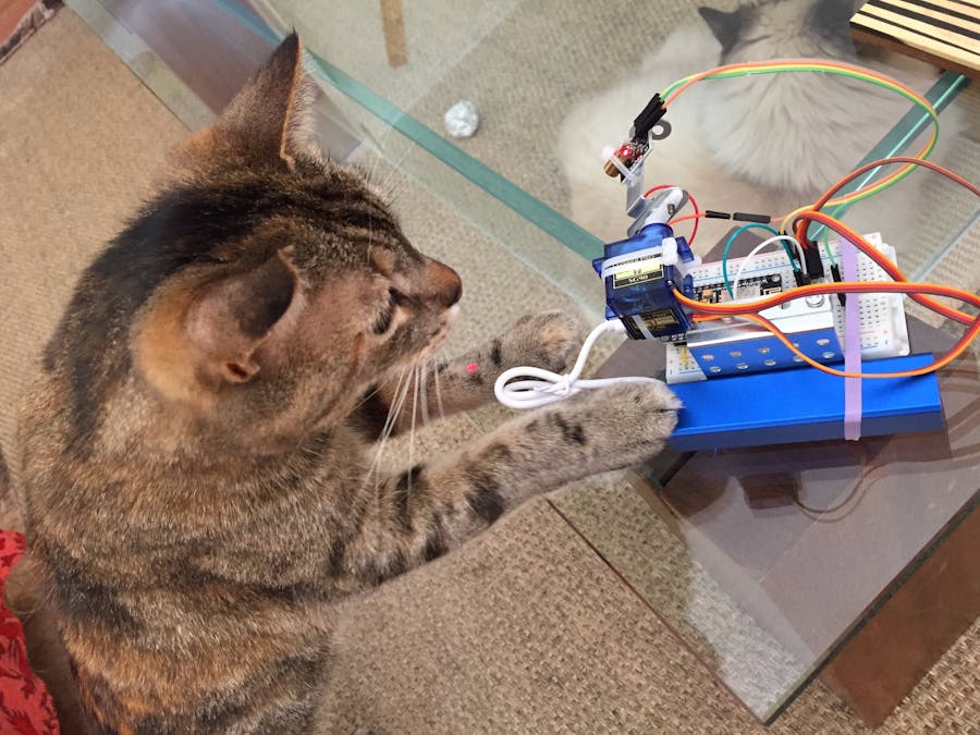
Below, we can see the cat playing with laserCat
:
Let's built a very simple Pan/Tilt mechanism, mounting the servos "one on top of the other" as shown in the pictures.
- The Pan Servo is used "as base". Keep it on Vertical.
- Fixed the Tilt Servo over the move part of Pan Servo (in horizontal position).
- Fixed the Laser Pointer at the "Tilt Servo" move part as shown.
Note that I used some used metal parts of a disassembled toy as base structure for the Pan/Tilt mechanism.
The HWThe circuit is very simple.
Before you start the connections, take in consideration that the nodeMCU
is powered with 5V, but it works internally (and its pins) with 3.3V. So, the Servos should not be sourced from one of its 3.3V output. The exception is the "Vin pin
", that can be either drive 5V to the breadboard +VCC rail or power the NodeMCU ID an external source is used.
The laser Point module should be powered with 5V, but here the 3.3V digital output of NodeMCU was enough to power it. BTW, doing that the laser power is lower and its use safer.
WARNING: The laser pointer can be dangerous for eyes if directly pointed to them. Protect yours, others and your animal's eyes. Use with care.
- Connect the Pan servo data ("
X" axis) to the NodeMCU Pin D1 (note that all digital pins of NodeMCU are PWM)
- Connect the Tilt servo data ("
Y" axis) to the NodeMCU Pin D2
- Connect the "
S" pin of Laser Pointer to NodeMCU Pin D3
- Connect the "
Vin" Pin of NodeMCU to Breadboard +5V Rail
- Connect the NodeMCU, Servos and Laser Pointers GND's to Breadboard GND Rail
- Connect the +5V Servos pins to Breadboard +5V Rail
The above circuit diagram shows the proper connections.
The codeFor the Servo's control, we will use the library Servo.h
, that will generate PWM signals easily positioning them with angular inputs. Once the base of the project is to use BLYNK, the code became very simple. We must define 4 virtual variables:
- V0: "X position"
- V1: "Y position"
- V2: "Random or manual" operation
- V3: Laser ON/OFF command
BLYNK_WRITE(V0)
{
  xPotReading = param.asInt();
}
BLYNK_WRITE(V1)
{
  yPotReading = param.asInt();
}
BLYNK_WRITE(V2)
{
  randState = param.asInt();
}
BLYNK_WRITE(V4)
{
  laserState = param.asInt();
}
If you do not know how the NodeMCU works with Arduino IDE, please see my tutorial: From blink to Blynk, an IoT jorney on the wings of NodeMCU ESP-12E
Below the complete code. Go through it. It is very simple to understand.
BlynkAs always, I hope this project can help others find their way in the exciting world of electronics and IoT! For more projects, please visit my blog: MJRoBot.org
Saludos from the south of the world!
See you at my next tutorial!
Thank you
Marcelo


Comments